
Dell™ Latitude™ V710/V740 Service Manual
|
NOTICE: For V740 only, prior to replacing the system board, ensure that a thermal pad is present on the Memory Controller Hub (MCH) heat-sink, located on the base plastics. If a thermal pad is already present, you do not need to replace it. |
The system board's BIOS chip contains the service tag sequence, which is also visible on a barcode label on the bottom of the computer. The replacement kit for the system board includes a CD that provides a utility for transferring the service tag sequence to the replacement system board.
|
NOTICE: Disconnect the computer and any attached devices from electrical outlets, and remove any installed batteries. |
|
NOTICE: To avoid ESD, ground yourself by using a wrist grounding strap or by touching an unpainted metal surface on the computer. |
|
NOTICE: Read "Preparing to Work Inside the Computer" before performing the following procedure. |
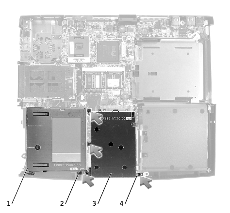
1 |
floppy drive cage |
2 |
M2.5 x 5-mm screws (2) |
3 |
hard drive cage |
4 |
M2.5 x 5-mm screws (2) |
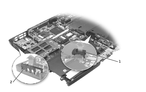
1 |
battery connector cover |
2 |
headphone/microphone bridge |
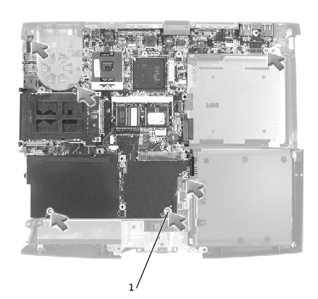
1 |
M2.5 x 4-mm screws (6) |
 |
NOTE: The M2.5 x 4 screws are silver. |
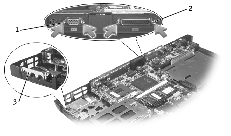
1 |
video-connector hex nuts |
2 |
parallel-connector hex nuts |
3 |
headphone/microphone flex-panel |
|
NOTICE: For V740 only, prior to replacing the system board, ensure that a thermal pad is present on the Memory Controller Hub (MCH) heat-sink, located on the base plastics. If a thermal pad is already present, you do not need to replace it. |
|
NOTICE: Secure the modem-cable grounding terminal to the system board with one of the six M2.5 x 4-mm screws labeled "circle L." Failure to do so may result in damage to the computer. |
|
NOTE: The M2.5 x 4 screws are silver. |
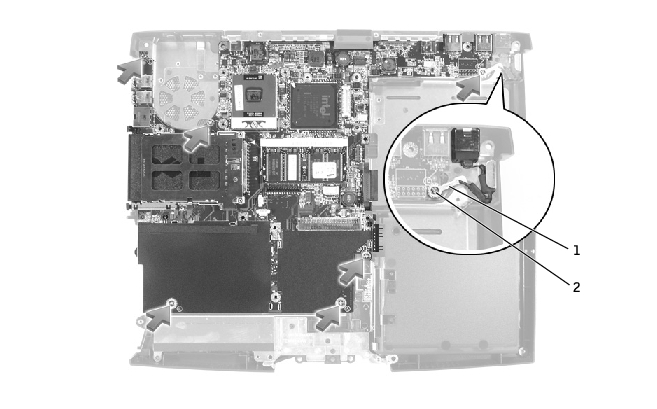
1 |
modem-cable grounding terminal |
2 |
M2.5 x 4-mm screws (6) |
|
NOTICE: Route cables so that they will not be crimped or pinched when the complete assembly is put back together. |
|
NOTICE: Before turning on the computer, replace all screws and ensure that no stray screws remain inside the computer. Failure to do so may result in damage to the computer. |
|
NOTE: After replacing the system board, enter the computer service tag sequence into the BIOS of the replacement system board. |