 EMI Shield
Dell™ Latitude™ V710/V740 Service Manual
 |
NOTICE: Disconnect the computer and any attached devices from electrical outlets, and remove any installed batteries. |
|
NOTICE: To avoid ESD, ground yourself by using a wrist grounding strap or by touching an unpainted metal surface on the computer. |
|
NOTICE: Read "Preparing to Work Inside the Computer" before performing the following procedure. |
|
NOTICE: When reconnecting the display-feed flex cable connector to the system board, push down on the top left and right ends of the connector. Pressing on the center of the connector may damage resistors and compromise EMI protection in the computer. |
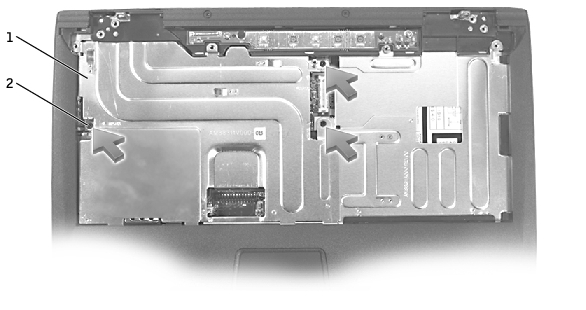
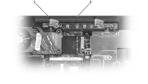
1 |
EMI shield |
2 |
M2.5 x 12-mm screws (3) |
|
NOTICE: Disconnect the computer and any attached devices from electrical outlets, and remove any installed batteries. |
|
NOTICE: To avoid ESD, ground yourself by using a wrist grounding strap or by touching an unpainted metal surface on the computer. |
|
NOTICE: Read "Preparing to Work Inside the Computer" before performing the following procedure. |
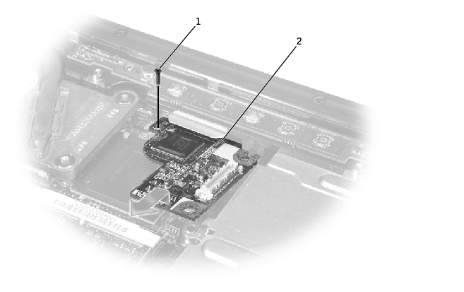
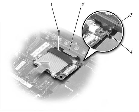
1 |
M2.5 x 5-mm screw (1) |
2 |
V710 video board |
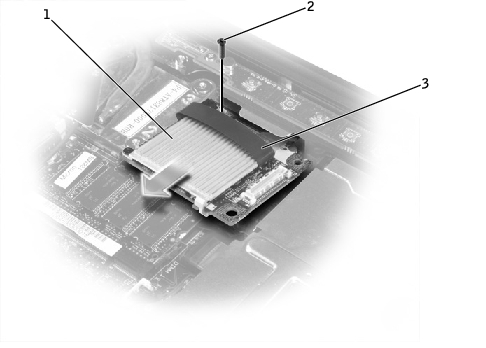
1 |
V740 video board |
2 |
M2.5 x 8-mm screw (1) |
3 |
pull tab |
1 |
M2.5 x 5-mm screw (1) |
2 |
palm rest |
3 |
top right corner of the V710 video board |
4 |
guide |
1 |
M2.5 x 8-mm screw (1) |
2 |
palm rest |
3 |
top right corner of the V740 video board |
4 |
guide |
|
NOTICE: For V740 only, before you connect the video board to the system board, ensure that you route the power- board flex cable under the memory module. |
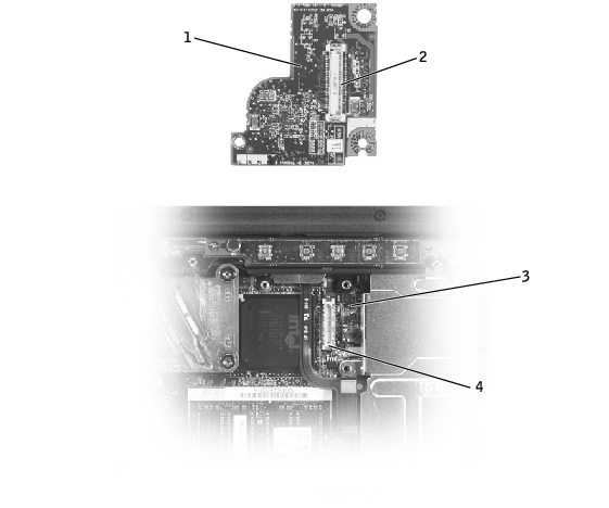
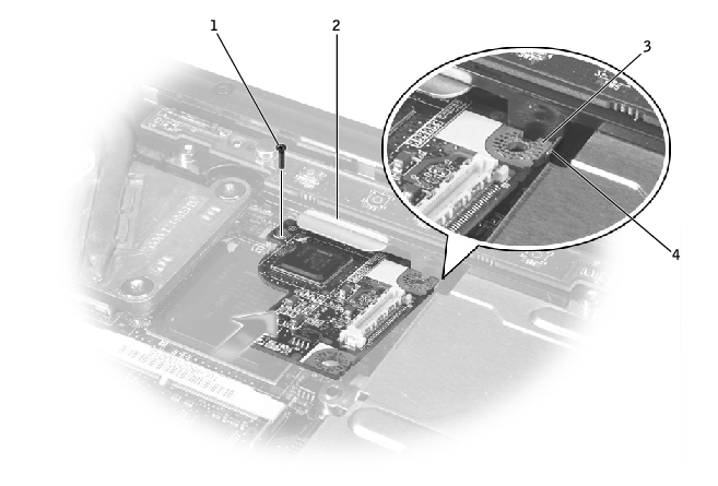
1 |
bottom of V710 video board |
2 |
video board connector |
3 |
system board |
4 |
interface connector |
|
NOTICE: For V740 only, before you connect the video board to the system board, ensure that you route the power- board flex cable under the memory module. |
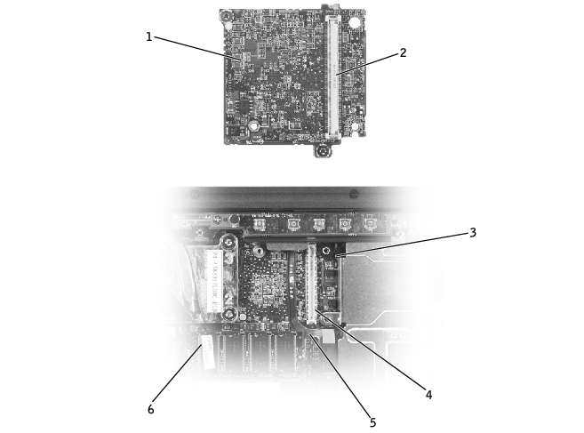
1 |
bottom of V740 video board |
2 |
video board connector |
3 |
system board |
4 |
interface connector |
5 |
power-board flex cable |
6 |
memory module |
|
NOTICE: Disconnect the computer and any attached devices from electrical outlets, and remove any installed batteries. |
|
NOTICE: To avoid ESD, ground yourself by using a wrist grounding strap or by touching an unpainted metal surface on the computer. |
|
NOTICE: Read "Preparing to Work Inside the Computer" before performing the following procedure. |
|
NOTICE: You must remove the display assembly before you remove the palm rest; the display hinges pass through the back of the palm rest. |
1 |
M2.5 x 5-mm screws (2) |
2 |
top of the palm rest |
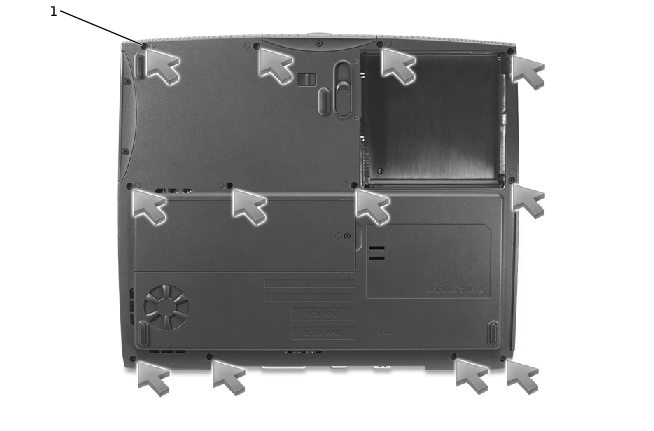
1 |
M2.5 x 8-mm screws (12) |
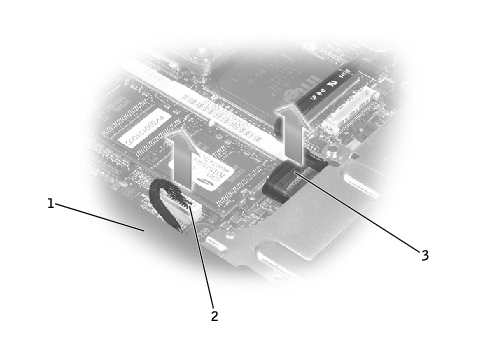
1 |
back center of the palm rest |
2 |
touch pad connector |
3 |
power board connector |
|
NOTICE: Carefully separate the palm rest from the bottom case to avoid damage to the palm rest. |