
Dell™ Latitude™ V710/V740 Service Manual
|
NOTICE: Disconnect the computer and any attached devices from electrical outlets, and remove any installed batteries. |
|
NOTICE: To avoid ESD, ground yourself by using a wrist grounding strap or by touching an unpainted metal surface on the computer. |
|
NOTICE: Read "Preparing to Work Inside the Computer" before performing the following procedure. |
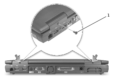
1 |
M2.5 x 5-mm screws (2) |
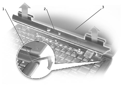
1 |
scalloped edge of center control cover |
2 |
center control cover |
3 |
display assembly |
 |
NOTE: The M2.5 x 4 screws are silver. |
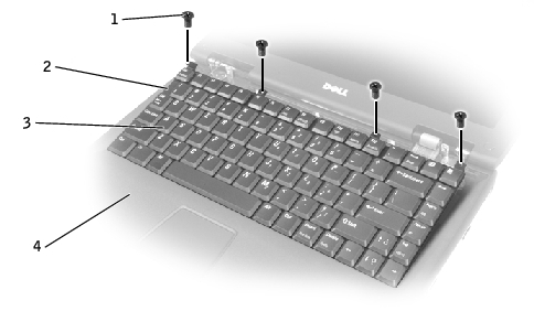
1 |
M2.5 x 4-mm screws (4) |
2 |
scalloped edge of blank key |
3 |
keyboard |
4 |
palm rest |
|
NOTICE: The keycaps on the keyboard are fragile, easily dislodged, and time-consuming to replace. Be careful when removing and handling the keyboard. |
|
NOTICE: Do not pull on the keyboard flex cable. |
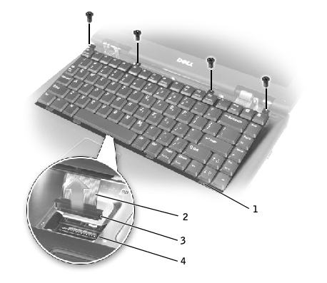
1 |
keyboard securing tabs (4) |
2 |
keyboard flex cable |
3 |
keyboard connector |
4 |
interface connector on system board |
|
NOTICE: The keycaps on the keyboard are fragile, easily dislodged, and time-consuming to replace. Be careful when handling and replacing the keyboard. |
|
NOTICE: To avoid damage to the connector pins, press the keyboard connector evenly into the interface connector on the system board, and do not reverse the keyboard connector. |
The keyboard connector may have a label on it that shows the correct orientation of the keyboard connector to the interface connector on the system board.
|
NOTICE: Position the keyboard flex cable so that it is not pinched when you replace the keyboard in the bottom case. |
Ensure that all four securing tabs are engaged in their respective slots before trying to completely seat the keyboard. Fitting the tabs to the slots may be easiest when viewed from above and slightly behind the front edge of the keyboard. Press down on the left and right ![]() keys to help control tab/slot alignment.
keys to help control tab/slot alignment.
When the keyboard appears to be completely seated, confirm that the front edge of the keyboard is aligned with the edge of the palm rest before proceeding.
|
NOTE: The M2.5 x 4 screws are silver. |
Ensure that the center control cover is snapped in properly so that it is flush with the keyboard.