Back to Contents Page

Before You Begin

Dell™ Latitude™ V710/V740 Service Manual

  Preparing to Work Inside the Computer

  Recommended Tools

  Computer Orientation

  Screw Identification


Preparing to Work Inside the Computer

CAUTION: Only a certified service technician should perform repairs on your computer. Damage due to servicing that is not authorized by Dell is not covered by your warranty. Read and follow applicable instructions in "Safety and EMC Instructions: Portable Computers" in the Latitude™ System Information Guide that came with the computer.
NOTICE: To avoid damaging the computer, perform the following steps before you begin working inside the computer.
  1. Ensure that the work surface is flat and clean to prevent scratching the computer cover.

  2. Save any work in progress and exit all open programs.

  3. Turn off the computer and all attached devices.

NOTE: Ensure that the computer is off and not in a power management mode. If you cannot shut down the computer using the computer operating system, press and hold the power button for 4 seconds.
  1. Disconnect the computer from the electrical outlet.

  2. To avoid possible damage to the system board, wait 10 to 20 seconds and then disconnect any attached devices.

  3. Disconnect all other external cables from the computer.

  4. Remove any installed PC Cards from the PC Card slot.

  5. Close the display and turn the computer upside down on a flat work surface.

NOTICE: To avoid damaging the system board, you must remove the main battery before you service the computer.
CAUTION: When you remove the battery, ensure that the computer is upside down on a flat work surface so that the battery does not fall out of the computer.
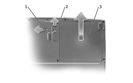
  1. Remove the battery:

    1. Unlock the battery.

    1. Slide and hold the battery latch release all the way up until the left edge of the battery pops up.

    2. Remove the battery.

1

battery lock

2

battery latch release

3

battery

  1. To dissipate any static electricity while you work, use a wrist grounding strap or periodically touch an unpainted metal surface.

  2. Handle components and cards with care. Do not touch the components or contacts on a card. Hold a card by its edges or by its metal mounting bracket. Hold a component such as a microprocessor by its edges, not by its pins.


Recommended Tools

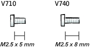
The procedures in this manual require the following tools:
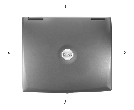

Computer Orientation

1

back

2

right

3

front

4

left


Screw Identification

When you are removing and replacing components, photocopy "Screw Identification" as a tool to lay out and keep track of the screws. The placemat provides the number of screws and their sizes.

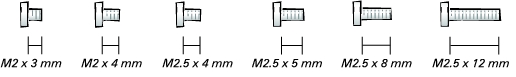
NOTICE: When reinstalling a screw, you must use a screw of the correct diameter and length. Ensure that the screw is properly aligned with its corresponding hole, and avoid overtightening.
NOTE: All M2.5 x 4 screws are silver, and all other screws are black.

Back-Panel Fan:

(2 each)

Hard Drive Door:

(1 each)

Memory Module/
Modem Cover:

(1 each)

Modem to System Board:

(2 each)

Optical Drive:

(1 each)

Floppy Drive:

(2 each)

Keyboard Assembly to Hinges:

(2 each)

Keyboard to
Bottom Case:

(4 each; silver screws)

Display Assembly
to Back Panel:

(2 each)

Display-Feed Flex Cable
to System Board:

(2 each)

Hinge Bracket to Bottom Case:

(4 each)

Display Bezel:

(5 each)

Screw Covers (5 each)

Display Panel:

(4 each)

Display-Feed Flex Cable to
Display Assembly:

(1 each)

Display Latch:

(2 each)

EMI Shield:

(3 each)

Top of Palm Rest to
Bottom Case:

(2 each)

Video Board
to Bottom Case:

(1 each)

Palm Rest to
Bottom Case:

(12 each)

Floppy Drive Cage to
Bottom Case:

(2 each)

Hard Drive Cage to
Bottom Case:

(2 each)

System Board to
Bottom Case:

(6 each; silver screws)

Battery Latch Assembly
to Bottom Case:

(1 each)


Back to Contents Page