 Display Assembly
Dell™ Latitude™ V710/V740 Service Manual
 |
NOTICE: You must remove the display assembly before you remove the palm rest. |
|
NOTICE: Disconnect the computer and any attached devices from electrical outlets, and remove any installed batteries. |
|
NOTICE: To avoid ESD, ground yourself by using a wrist grounding strap or by touching an unpainted metal surface on the computer. |
|
NOTICE: Read "Preparing to Work Inside the Computer" before performing the following procedure. |
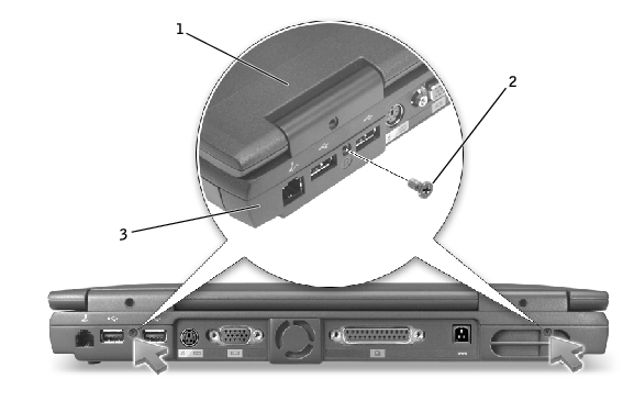
1 |
top cover |
2 |
M2.5 x 5-mm screws (2) |
3 |
bottom case |
|
NOTICE: When reconnecting the display-feed flex cable connector to the system board, push down on the top left and right ends of the connector. Pressing on the center of the connector may damage resistors and compromise EMI protection in the computer. |
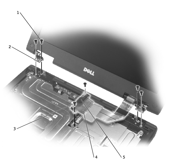
1 |
M2.5 x 5-mm screws (4) |
2 |
hinge blocks (2) |
3 |
M2.5 x 5-mm screws (2) |
4 |
display-feed flex cable |
5 |
pull tab |
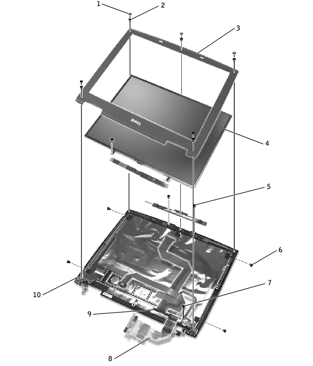
1 |
screw covers (5) |
6 |
M2 x 3-mm screws (4) |
2 |
M2.5 x 5-mm screws (5) |
7 |
M2.5 x 5-mm screw (1) |
3 |
display bezel |
8 |
display-feed flex cable |
4 |
display panel |
9 |
flex-cable retention bracket |
5 |
M2.5 x 5-mm screws (2) |
10 |
top cover |
|
NOTICE: Disconnect the computer and any attached devices from electrical outlets, and remove any installed batteries. |
|
NOTICE: To avoid ESD, ground yourself by using a wrist grounding strap or by touching an unpainted metal surface on the computer. |
|
NOTICE: Read "Preparing to Work Inside the Computer" before performing the following procedure. |
|
NOTICE: Carefully separate the bezel from the top cover to avoid damage to the bezel. |
|
NOTICE: Disconnect the computer and any attached devices from electrical outlets, and remove any installed batteries. |
|
NOTICE: To avoid ESD, ground yourself by using a wrist grounding strap or by touching an unpainted metal surface on the computer. |
|
NOTICE: Read "Preparing to Work Inside the Computer" before performing the following procedure. |
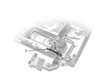
1 |
flex-cable retention bracket |
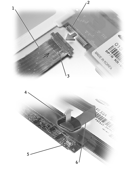
1 |
top flex cable connector |
2 |
display panel connector |
3 |
pull tab |
4 |
pull tab |
5 |
inverter connector on system board |
6 |
bottom flex cable connector |
|
NOTICE: Disconnect the computer and any attached devices from electrical outlets, and remove any installed batteries. |
|
NOTICE: To avoid ESD, ground yourself by using a wrist grounding strap or by touching an unpainted metal surface on the computer. |
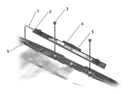
1 |
spring |
2 |
spring hook (display latch) |
3 |
M2.5 x 5-mm screws (2) |
4 |
display latch |
5 |
bracket |
6 |
spring hook (top cover) |