 Memory Module
Dell™ Latitude™ V710/V740 Service Manual
 |
NOTE: This procedure covers removing and replacing the memory module located under the memory module/modem cover on the bottom of the computer. A second memory module resides on the upper surface of the system board under the EMI shield. To replace the memory module under the EMI shield, perform the procedure for removing the EMI shield. Then replace the memory module. |
 |
NOTICE: Disconnect the computer and any attached devices from electrical outlets, and remove any installed batteries. |
|
NOTICE: To avoid ESD, ground yourself by using a wrist grounding strap or by touching an unpainted metal surface on the computer. |
|
NOTICE: Read "Preparing to Work Inside the Computer" before performing the following procedure. |
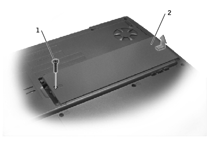
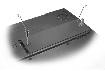
1 |
M2.5 x 5-mm screw |
2 |
memory module/modem cover |
|
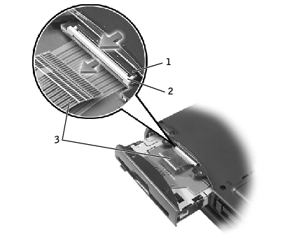
NOTICE: To prevent damage to the memory module connector, do not use tools to spread the inner metal tabs that secure the memory module. |
|
NOTICE: Handle memory modules by their edges, and do not touch the components on a module. |
The module should pop up.
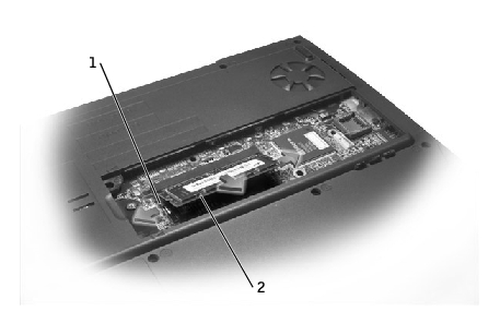
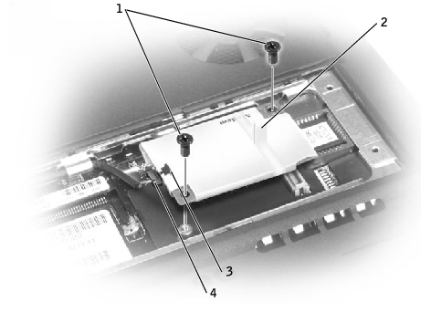
1 |
securing clip |
2 |
memory module |
|
NOTICE: If the memory module/modem cover is difficult to close, remove the module and reinstall it. Forcing the cover to close may damage your computer. |
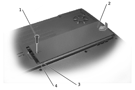
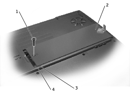
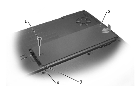
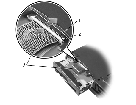
1 |
M2.5 x 5-mm screw |
2 |
memory module/modem cover |
3 |
arrows (2) |
4 |
lines (2) |
As the computer boots, it detects the additional memory and automatically updates the system configuration information.

|
CAUTION: Before performing these procedures, turn off the computer, disconnect it from the electrical outlet, and disconnect the modem from the telephone wall jack. |
|
NOTICE: Disconnect any attached devices from electrical outlets, and remove any installed batteries. |
|
NOTICE: To avoid ESD, ground yourself by using a wrist grounding strap or by touching an unpainted metal surface on the computer. |
|
NOTICE: Read "Preparing to Work Inside the Computer" before performing the following procedure. |
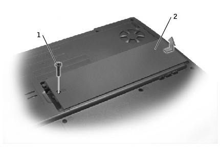
1 |
M2.5 x 5-mm screw |
2 |
memory module/modem cover |
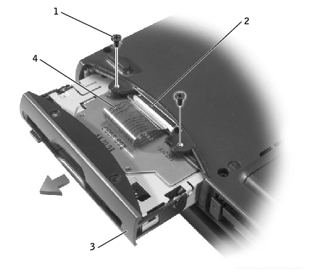
1 | M2 x 3-mm screws (2) |
2 | pull tab |
3 | modem cable connector |
4 | modem cable |
|
NOTICE: The cable connectors are keyed for correct insertion; do not force the connections. |
Install the two M2 x 3-mm screws to secure the modem to the system board.
|
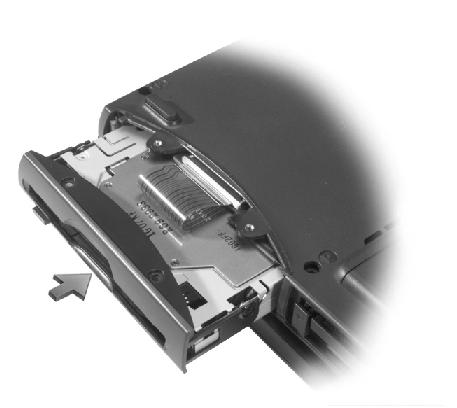
NOTICE: Replace the memory module/modem cover so that it is seated properly around the edges and does not bulge near the center of the cover. Tightening the memory-module/modem cover screw when the cover is improperly seated can damage your computer. |
1 |
M2.5 x 5-mm screw |
2 |
memory module/modem cover |
3 |
arrows (2) |
4 |
lines (2) |
|
NOTICE: To avoid ESD, ground yourself by using a wrist grounding strap or by touching an unpainted metal surface on the computer. |
|
NOTICE: Read "Preparing to Work Inside the Computer" before performing the following procedure. |
|
NOTICE: Disconnect the computer and attached devices from electrical outlets, and remove any installed batteries. |
1 |
M2.5 x 5-mm screw |
2 |
memory module/modem cover |
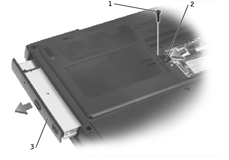
1 |
M2.5 x 8-mm screw |
2 |
optical-drive release button |
3 |
optical drive |
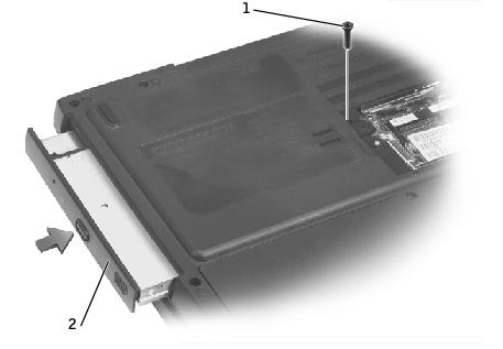
1 |
M2.5 x 8-mm screw |
2 |
optical drive |
|
NOTICE: Replace the memory module/modem cover so that it is seated properly around the edges and does not bulge near the center of the cover. Tightening the memory-module/modem cover screw when the cover is improperly seated can damage your computer. |
1 |
M2.5 x 5-mm screw |
2 |
memory module/modem cover |
3 |
arrows (2) |
4 |
lines (2) |
|
NOTICE: To avoid ESD, ground yourself by using a wrist grounding strap or by touching an unpainted metal surface on the computer. |
|
NOTICE: Read "Preparing to Work Inside the Computer" before performing the following procedure. |
|
NOTICE: Disconnect the computer and attached devices from electrical outlets, and remove any installed batteries. |
|
NOTICE: Ensure that you disconnect the flex cable from the ZIF connector before you remove the floppy drive from the computer. See step 3 for further instructions. |
1 |
M2.5 x 5-mm screws (2) |
2 |
ZIF connector |
3 |
floppy drive |
4 |
flex cable |
|
NOTICE: Release the securing tab before you disconnect the flex cable from the ZIF connector. Failure to do so can damage the ZIF connector. |
1 |
ZIF connector |
2 |
securing tab |
3 |
flex cable |
|
NOTE: If you do not connect the flex cable to the ZIF connector properly, your floppy drive will not function properly. |
Ensure that you insert the flex cable into the ZIF connector and not below the ZIF connector.
1 |
ZIF connector |
2 |
securing tab |
3 |
flex cable |
If the computer does not detect the floppy drive, you may have improperly inserted the flex cable. If so, disconnect the flex cable and reconnect it to the ZIF connector.