
Dell™ Latitude™ V710/V740 Service Manual
|
NOTICE: Disconnect the computer and any attached devices from electrical outlets, and remove any installed batteries. |
|
NOTICE: To avoid ESD, ground yourself by using a wrist grounding strap or by touching an unpainted metal surface on the computer. |
|
NOTICE: Read "Preparing to Work Inside the Computer" before performing the following procedure. |
|
NOTICE: Do not touch the processor die. Press and hold the microprocessor down on the substrate on which the die is mounted while turning the cam screw to prevent intermittent contact between the cam screw and microprocessor. |
|
NOTICE: To avoid damage to the microprocessor, hold the screwdriver so that it is perpendicular to the microprocessor when turning the cam screw. |
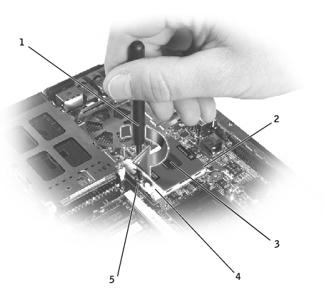
1 |
screwdriver (perpendicular to microprocessor) |
2 |
pin-1 corner |
3 |
processor die (do not touch) |
4 |
ZIF socket |
5 |
ZIF-socket cam screw |
|
NOTICE: To ensure maximum cooling for the microprocessor, do not touch the heat transfer areas on the microprocessor thermal-cooling assembly. The oils in your skin reduce the heat transfer capability of the thermal pads. |
|
NOTICE: When removing the microprocessor module, pull the module straight up. Be careful not to bend the pins on the microprocessor module. |
The ZIF-socket cam screw secures the microprocessor to the system board. Take note of the arrow on the ZIF-socket cam screw.
|
NOTICE: Ensure that the cam lock is in the fully open position before seating the microprocessor module. Seating the microprocessor module properly in the ZIF socket does not require force. |
|
NOTICE: A microprocessor module that is not properly seated can result in an intermittent connection, or permanent damage to the microprocessor and ZIF socket. |
 |
NOTE: The pin-1 corner of the microprocessor module has a triangle that aligns with the triangle on the pin-1 corner of the ZIF socket. |
|
NOTICE: You must position the microprocessor module correctly in the ZIF socket to avoid permanent damage to the module and the socket. |
When the microprocessor module is correctly seated, all four corners are aligned at the same height. If one or more corners of the module are higher than the others, the module is not seated correctly.
|
NOTICE: Hold the microprocessor down while turning the cam screw to prevent intermittent contact between the cam screw and microprocessor. |