
Dell™ Latitude™ C840 Service Manual
|
NOTICE: Disconnect the computer and attached devices from electrical outlets and remove any installed batteries. |
|
NOTICE: To avoid ESD, ground yourself by using a wrist grounding strap or by periodically touching unpainted metal on the computer. |
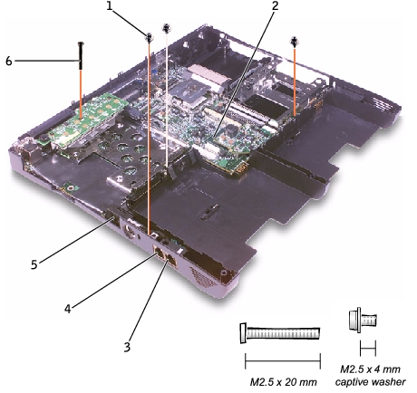
1 |
M2.5 x 4-mm captive-washer screws (3) |
2 |
system board |
3 |
network connector |
4 |
modem connector |
5 |
network cable cover |
6 |
M2.5 x 20-mm screw |
The BIOS chip on the system board contains the service tag sequence, which is also visible on a bar code label on the bottom of the computer.
The replacement kit for the system board includes a floppy disk or CD that provides a utility for transferring the service tag sequence to the replacement system board.
|
NOTICE: If you received a flash BIOS update floppy disk or CD with the replacement microprocessor, you must update the BIOS after replacing the microprocessor module. |

1 |
network cable cover |
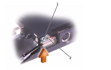
1 |
outer corner of upper connector |
2 |
network cable |
If necessary to help release the system board, pull outward on the top of the plastic near the back left corner of the bottom case (see the small arrow at the far left in the following figure).
