 Preparing to Work Inside the Computer
Dell™ Latitude™ C840 Service Manual
Preparing to Work Inside the Computer

|
CAUTION: Only a certified service technician should perform repairs on your computer. Damage due to servicing that is not authorized by Dell is not covered by your warrantly. Read and follow all safety instructions in "Safety and EMC Instructions: Portable Computers" in your System Information Guide. |
 |
NOTICE: To avoid damaging the computer, perform the following steps before you begin working inside the computer. |
 |
NOTE: Before turning off the computer, ensure that the computer is not in a power-management mode. |
|
NOTICE: To avoid component damage, always remove any installed batteries before you service the computer. |
The procedures in this document require the following tools:
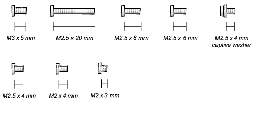
When you are removing and replacing components, photocopy the placemat as a tool to lay out and keep track of the component screws. The placemat provides the number of screws and the sizes.
|
NOTICE: When reinstalling a screw, you must use a screw of the correct diameter and length. Ensure that the screw is properly aligned with its corresponding hole, and avoid overtightening. |
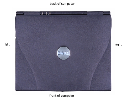
Hard-Drive Door Security: M3 x 5 mm (1 each)
| Keyboard to Bottom Case: M2.5 x 20 mm (4 each; one in memory door and one in Mini PCI door)
| Display to Bottom Case: M2.5 x 6 mm (3 each; 2 at back of computer; 1 at display flex-cable strain relief)
|
Display Bezel: Rubber screw covers (4 each) Plastic screw covers (2 each) M2.5 x 4 mm (6 each)
| Display Panel to Display Mounting Bracket: M2 x 3 mm (6 each)
Flex-Cable Mounting Bracket to Top Cover: M2.5 x 4 mm (1 each)
| Video Graphics Board: M2.5 x 8 (3 each)
|
Palm Rest to M2.5 x 20 mm (9 each)
Palm Rest Bracket:
| System Board: M2.5 x 4 mm captive washer
M2.5 x 20 mm (1 each)
| LED Board: M2 x 4 mm (2 each)
|
Fan: M2 x 4 mm (3 each)
| Memory Module/Modem Cover: M2.5 x 20 mm (1 each)
| Modem Daughter Card: M2 x 3 mm (1 each)
|
Mini PCI Card: M2.5 x 20 mm (1 each)
|
|
|