 Display Overview
Dell™ Latitude™ C840 Service Manual
 |
NOTICE: Disconnect the computer and attached devices from electrical outlets and remove any installed batteries. |
|
NOTICE: To avoid ESD, ground yourself by using a wrist grounding strap or by periodically touching unpainted metal on the computer. |
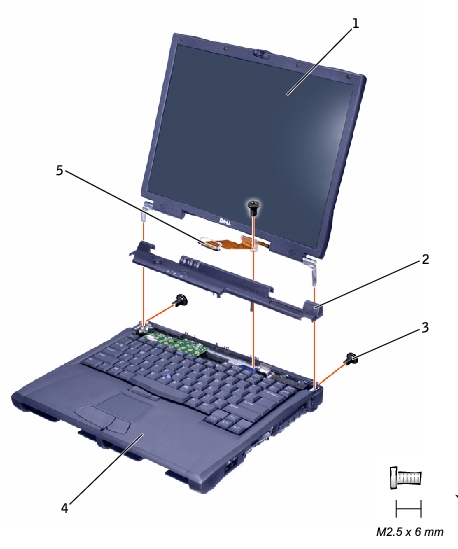
1 | display |
2 | hinge cover |
3 | M2.5 x 6-mm screws (3) |
4 | bottom case |
5 | display flex cable |
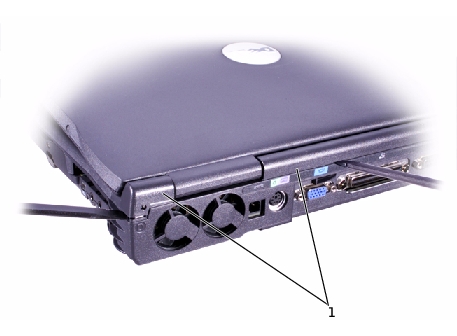
1 | hinge cover |
1 | M2.5 x 6-mm screws (2) |
|
NOTICE: Remove the display flex cable before you remove the display assembly. |
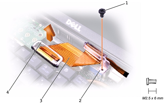
1 |
M2.5 x 6-mm screw |
2 |
strain relief |
3 |
display flex cable |
4 |
pull loop |
|
NOTICE: When reconnecting the flex cable, press down on both ends of the connector, not in the middle. Pressing the middle of the connector can damage fragile components. |
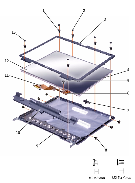
1 |
M2.5 x 4-mm screws (6) |
8 |
M2 x 3-mm screws (6) |
2 |
rubber screw covers (4) |
9 |
top cover |
3 |
display bezel |
10 |
hinge cover |
4 |
plastic tabs (6) |
11 |
display flex cable |
5 |
M2.5 x 4-mm screw |
12 |
display panel |
6 |
flex-cable mounting bracket |
13 |
plastic screw covers (2) |
7 |
display latch |
|
|
The bezel is secured to the top cover with plastic tabs around the sides. Use a plastic scribe to help separate the bezel from the top cover.
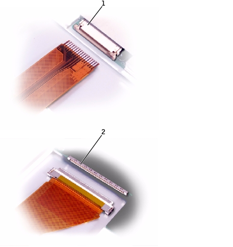
1 |
ZIF connector |
2 |
standard connector |
 |
NOTE: Use a magnetic screwdriver to reassemble the display panel in the display. |

