
Dell™ Latitude™ C840 Service Manual
|
NOTICE: Disconnect the computer and attached devices from electrical outlets and remove any installed batteries. |
|
NOTICE: To avoid ESD, ground yourself by using a wrist grounding strap or by periodically touching unpainted metal on the computer. |
|
NOTICE: To ensure maximum cooling for the microprocessor, do not touch the heat transfer areas on the microprocessor thermal-cooling assembly. The oils in your skin reduce the heat transfer capability of the thermal pads. |
|
NOTICE: When removing the microprocessor module, pull the module straight up. Do not bend the pins. |
|
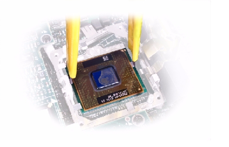
NOTICE: To avoid damage to the microprocessor, hold the screwdriver so that it is perpendicular to the microprocessor when loosening the cam screw (see "Microprocessor Cam Screw"). |
Microprocessor Cam Screw (Example)
|
NOTICE: Hold the microprocessor down while turning the cam screw to prevent intermittent contact between the cam screw and microprocessor. |
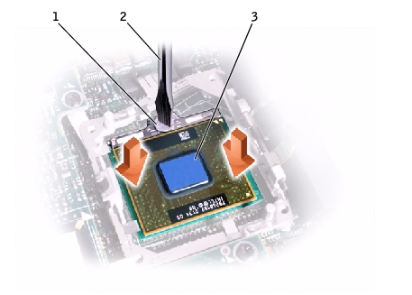
1 |
cam screw |
2 |
perpendicular screwdriver |
3 |
processor die (do not touch) |
|
NOTICE: If you received a flash BIOS update floppy disk or CD with the replacement microprocessor, you must update the BIOS after replacing the microprocessor module. |
|
NOTICE: Proper seating of the microprocessor module does not require force. |
|
NOTICE: A microprocessor module that is not properly seated can result in an intermittent connection and subsequent failures. |
When the microprocessor module is correctly seated, all four corners are aligned to the same height. If one or more corners of the module are higher than the others, the module is not seated correctly.
|
NOTICE: Hold the microprocessor down while turning the cam screw to prevent intermittent contact between the cam screw and microprocessor (see "Microprocessor Cam Screw"). |
|
NOTICE: Do not over- or undertighten the screw. Tighten the screw until the screw indicator points to the "closed" or "locked" indicator on the socket. |
Closing the Microprocessor Retaining Clip
