Back to Contents Page
Dell™ Latitude™ C840
Service Manual
 Memory Modules
 Modem Daughter Card
 Mini PCI Card
 |
NOTICE: Disconnect the computer and any attached devices from electrical
outlets and remove any installed batteries.
|
 |
NOTICE: To avoid ESD, ground yourself by using a wrist grounding strap or
by periodically touching unpainted metal on the computer.
|
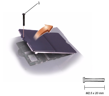
- Follow the instructions in "Preparing to Work Inside the Computer."
- Remove the M2.5 x 20-mm screw from the memory module/modem
cover.
- Disengage the metal tabs at the opposite end of the cover.
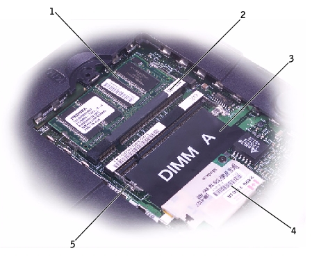
1 |
DIMM B |
2 |
memory module sockets (2) |
3 |
DIMM A socket |
4 |
modem daughter card |
5 |
metal tabs (2 per socket) |
- Remove the memory module/modem cover.
- To release a memory module from its socket, spread apart the tabs at
each side of the module until the module pops up slightly.
- Lift the memory module out of its socket.
- If you only have one memory module, install it in the socket labeled
"DIMM A." Install a second memory module in the socket labeled
"DIMM B."
 |
NOTE: Memory modules are keyed to fit into their sockets in only one
direction.
|
- Insert the memory-module edge connector into the socket slot at a
45-degree angle and press the module firmly into the slot.
- Pivot the module down until it clicks into place. If you do not hear a
click, remove the module and reinstall it.
- Insert the metal tabs on the memory module/modem cover into the
bottom case, rotate the cover down, and replace the M2.5 x 20-mm
screw.
 |
NOTICE: Disconnect the computer and any attached devices from electrical
outlets and remove any installed batteries.
|
 |
NOTICE: To avoid ESD, ground yourself by using a wrist grounding strap or
by periodically touching unpainted metal on the computer.
|
- Follow the instructions in "Preparing to Work Inside the Computer."
- Turn the computer over and remove the memory module/modem
cover.
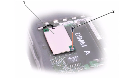
1 |
modem daughter card |
2 |
M2 x 3-mm screw |
- Remove the M2 x 3-mm screw that secures the modem daughter card
to the system board.
- Use the pull tab to pull the modem daughter card straight up out of its
connector.
 |
NOTICE: Do not pull on the modem cable. Pull the connector on the end of
the cable to disconnect the cable.
|
- Disconnect the modem cable from the modem daughter card.
 |
NOTICE: The cable connectors are keyed for correct insertion. Do not force
the connections.
|
- Connect the modem cable to the modem daughter card.
- Use the screw and boss holes at opposite corners of the modem
daughter card to align the card, and press the card into its connector
on the system board.
- Install the M2 x 3-mm screw that secures the card to the system board.
- Replace the memory module/modem cover.
You must remove the optional Mini PCI wireless modem (if installed) before the system board can be removed. A wireless modem card must be connected to the internal antenna of the computer.
 |
NOTICE: Disconnect the computer and attached devices from electrical
outlets and remove any installed batteries.
|
 |
NOTICE: To avoid ESD, ground yourself by using a wrist grounding strap or
by periodically touching unpainted metal on the computer.
|
Mini PCI Card Cover
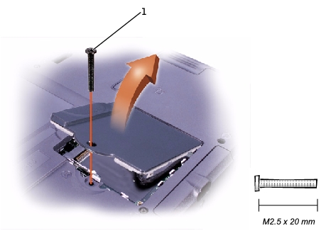
- Follow the instructions in "Preparing to Work Inside the Computer."
- Remove the M2.5 x 20-mm screw and then remove the Mini PCI card
cover.
- To release the Mini PCI card, spread the metal securing tabs until the
card pops up slightly.
- Disconnect the card from the internal antenna.
- Lift out the card and disconnect any attached cables.
- Align the Mini PCI card with the socket at a 45-degree angle, and press
the Mini PCI card into the socket.
- Connect the internal-antenna cable to the primary-antenna connector
on the card.
 |
NOTICE: The connectors are keyed for correct insertion; do not force the
connections.
|
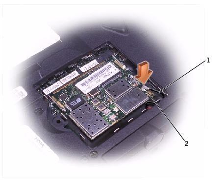
1 |
internal-antenna cable |
2 |
primary-antenna connector on card |
- Pivot the Mini PCI card down until it clicks into place.
- Replace the Mini PCI card cover and the M2.5 x 20-mm screw.
Back to Contents Page
 Memory Modules


