Back to Contents Page
Dell™ Latitude™ C610/C510
Service Manual
 Display Assembly
Display Latch
Hinge Covers
 |
NOTICE: You must remove the display assembly before you remove the palm
rest.
|
|
NOTICE: Disconnect the computer and any attached devices from electrical
outlets, and remove any installed batteries.
|
|
NOTICE: To avoid ESD, ground yourself by using a wrist grounding strap or
by touching an unpainted metal surface on the computer.
|
Display Assembly
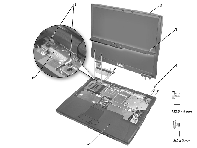
1 | M2 x 3-mm screws (4) |
2 | top cover |
3 | center control cover |
4 | M2.5 x 5-mm screws (5) |
5 | bottom case |
6 | EMI shield bracket |
- Remove the hard drive.
- Remove the center control cover.
- Remove the keyboard.
- Close the display.
- From the back of the computer, remove the five M2.5 x 5-mm screws
labeled "circle D."
- Open the display assembly approximately 180 degrees and support the
display assembly so that it does not open past this position.
- Remove the two M2 x 3-mm screws on the EMI shield bracket, which
is attached to the display-feed flex cable (see "Display Assembly").
- Remove the two M2 x 3-mm screws that secure the display-feed flex
cable to the system board (see "Display-Feed Flex Cable Connector").
Display-Feed Flex Cable Connector
|
NOTICE: When reconnecting the display-feed flex cable connector to the
system board, push down on the top left and right ends of the connector.
Pressing on the center of the connector may damage resistors and compromise
EMI protection in the computer.
|

- Pull up on the pull tab that is attached to the display-feed flex cable
connector to remove it from the interface connector on the system
board.
- Lift the display assembly up and out of the bottom case.
14.1-Inch Display Bezel and Panel

1 | rubber screw covers (6) | 5 | M2 x 4-mm screws (5) |
2 | M2.5 x 5-mm screws (6) | 6 | display-feed flex cable |
3 | display bezel | 7 | flex-cable retention bracket |
4 | top cover | 8 | display panel |
|
NOTICE: Disconnect the computer and any attached devices from electrical
outlets, and remove any installed batteries.
|
|
NOTICE: To avoid ESD, ground yourself by using a wrist grounding strap or
by touching an unpainted metal surface on the computer.
|
- Remove the hard drive.
- Remove the display assembly.
- Use a plastic scribe to pry the six rubber screw covers out of the screw
holes located on the front of the bezel.
- Remove the six M2.5 x 5-mm screws located on the front of the bezel.
|
NOTICE: Carefully separate the bezel from the top cover to avoid damage to
the bezel.
|
- Starting at the bottom of the display panel (by the Dell™ logo), use
your fingers to separate the bezel from the top cover by lifting up the
inside of the bezel while pushing in on the outside.
|
NOTICE: Disconnect the computer and any attached devices from electrical
outlets, and remove any installed batteries.
|
|
NOTICE: To avoid ESD, ground yourself by using a wrist grounding strap or
by touching an unpainted metal surface on the computer.
|
- Remove the hard drive.
- Remove the display assembly.
- Remove the display bezel.
- Remove the hinge covers.
- Remove the two M2 x 4-mm screws on the left side of the display
panel and the two M2 x 4-mm screws on the right side of the display
panel.
 |
NOTE: If you have a Hitachi display panel, remove the two M2 x 4-mm
screws from the center of the left side of the display panel.
|
- Remove the M2 x 4-mm screw that secures the display-feed flex cable
to the display assembly through the black plastic flex-cable retention
bracket (see "14.1-Inch Display Bezel and Panel").
- Lift from the top and rotate the display panel out of the top cover.
- Disconnect the bottom flex cable connector from the inverter
connector by pulling straight up on the attached pull tab (see
"Display-Feed Flex Cable Connections").
Display-Feed Flex Cable Connections
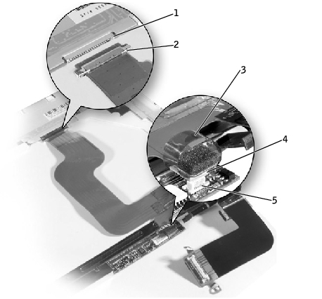
1 | display panel connector |
2 | top flex cable connector |
3 | pull tab |
4 | bottom flex cable connector |
5 | inverter connector |
- Remove the tape that secures the display panel connector and the tape
that secures the middle of the display-feed flex cable to the display
panel.
- Pull the top flex cable connector down and away to remove it from the
display panel connector.
- Reconnect the top flex cable connector to the display panel connector.
- Reconnect the bottom flex cable connector to the inverter connector.
- Replace the tape that secures the display panel connector and the tape
that secures the middle of the display-feed flex cable to the display
panel.
- Place the bottom edge of the display panel in the bottom of the top
cover and elevate the top of the panel with your hand.
- Lay the display panel in the top cover.
- Reinstall the five M2 x 4-mm screws that secure the display panel to
the top cover.
|
NOTICE: Disconnect the computer and any attached devices from electrical
outlets, and remove any installed batteries.
|
|
NOTICE: To avoid ESD, ground yourself by using a wrist grounding strap or
by touching an unpainted metal surface on the computer.
|
- Remove the hard drive.
- Remove the display assembly.
- Remove the display bezel.
- Remove the two M2.5 x 5-mm screws and the two M1.7 x 3.5-mm
screws that secure the display latch and bracket to the top cover.
- Lift the display latch and bracket up and out of the top cover.
Display Latch Removal (14.1-Inch XGA Panel Shown)
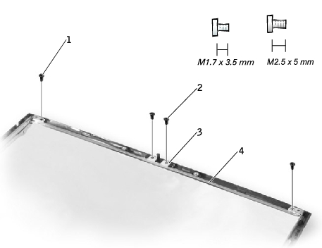
1 | M1.7 x 3.5-mm screws (2) |
2 | M2.5 x 5-mm screws (2) |
3 | display latch |
4 | bracket |
- On 14.1-inch XGA panels, place the display latch on top of its screw
holes, and then place the bracket on top of the display latch, aligning
the bracket and display latch screw holes.
On 14.1-inch SXGA+ panels, align the screw holes and place the display latch and attached bracket in the top cover.
- Replace the two M2.5 x 5-mm screws and the two M1.7 x 3.5-mm
screws that secure the display latch and bracket to the top cover.
- Remove the display assembly.
- Rotate the hinges forward at an angle of approximately 90 degrees to
the front of the display assembly.
- To remove the hinge covers, slide them off the hinges.
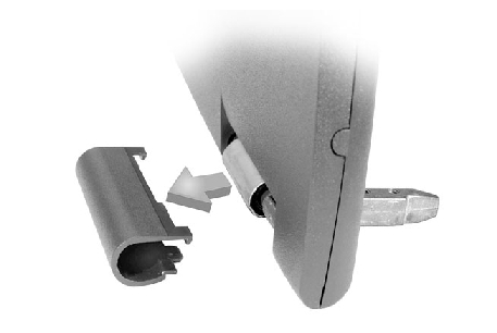
Hinge Cover Removal
- Attach the display assembly to the bottom case.
- Close the display assembly.
- Snap the hinge covers in place over the hinges.
|
NOTE: The right plastic hinge cover label includes an "R," and the left
plastic hinge cover label includes an "L." The hinge cover labels face the
back of the computer.
|
Hinge Cover Replacement
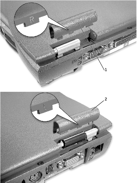
1 | right hinge cover |
2 | left hinge cover |
Back to Contents Page