Back to Contents Page
Dell™ Latitude™ C610/C510
Service Manual
 Removing the Keyboard
Replacing the Keyboard
 |
NOTICE: Disconnect the computer and any attached devices from electrical
outlets, and remove any installed batteries.
|
|
NOTICE: To avoid ESD, ground yourself by using a wrist grounding strap or
by touching an unpainted metal surface on the computer.
|
- Remove the hard drive.
- Turn the computer over, and remove the five M2.5 x 12-mm screws
labeled "circle K."
Screw Removal

- Turn the computer over and open the display.
|
NOTICE: The key caps on the keyboard are fragile, easily dislodged, and
time-consuming to replace. Be careful when removing and handling the
keyboard.
|
- Remove the center control cover.
- Use a small, flat-blade screwdriver or plastic scribe to lift the right
edge of the center control cover and pry it loose from the bottom
case.
- Lift the center control cover up and away from the bottom case.
Center Control Cover Removal

- To release the keyboard from the palm rest, use a small, flat-blade
screwdriver or plastic scribe to pull up on the scalloped edge of the
blank key on the keyboard.
Keyboard Removal
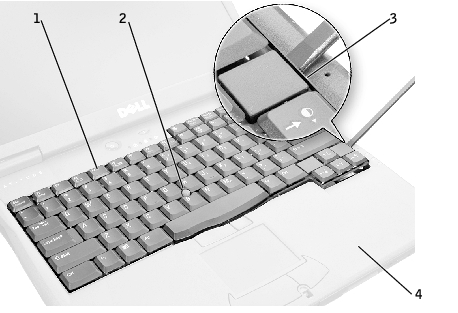
1 | keyboard |
2 | track stick |
3 | scalloped edge of blank key |
4 | palm rest |
- Lift the keyboard straight up until it clears the keyboard boss support
in the bottom case.
- Rotate the keyboard forward toward the front of the computer.
- Rest the key face of the keyboard on the palm rest.
|
NOTICE: Do not pull on the keyboard flex and track stick cables.
|
- Pull up on the keyboard connector to disconnect it from the interface
connector on the system board.
Keyboard Connector Removal
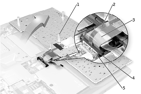
1 | boss support (5) |
2 | track stick cable |
3 | keyboard flex cable |
4 | keyboard connector |
5 | orientation label |
- Remove the keyboard from the bottom case.
- Place the keyboard on the palm rest at the front of the computer with
the keys face down and the connector toward the back of the
computer.
|
NOTICE: To avoid damage to the connector pins, press the keyboard
connector evenly into the interface connector on the system board, and do not
reverse the keyboard connector.
|
- Connect the keyboard connector to the interface connector on the
system board.
The keyboard connector may have a label on it that shows the correct orientation of the keyboard connector to the system-board interface connector.
- Carefully turn the keyboard over. Align the keyboard boss support, fit
the left side of the keyboard into place, and then snap the right side of
the keyboard into place.
|
NOTICE: Position the keyboard flex and track stick cables so that they are
not pinched when you replace the keyboard in the bottom case.
|
- Check that the keyboard is correctly installed. The keys should be flush
with the left and right surfaces of the palm rest.
- Replace the center control cover, close the display assembly, and turn
the computer over.
- Reinstall the five M2.5 x 12-mm screws in the holes labeled "circle K."
Back to Contents Page