 Removing the Memory Module/Modem Cover
Dell™ Latitude™ C400 Service Manual
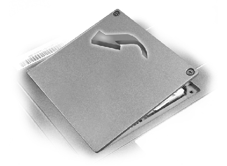
Removing the Memory Module/Modem Cover
Removing the Modem Daughter Card
Replacing the Modem Daughter Card
 |
NOTE: This procedure covers removing and replacing the memory module located under the memory module/modem cover on the bottom of the computer. A second memory module resides on the upper surface of the system board under the critical component shield. To replace the memory module under the critical component shield, perform the procedure for removing the palm rest up to and including removal of the critical component shield. Then replace the memory module. |
 |
NOTICE: Disconnect the computer and any attached devices from electrical outlets, and remove any installed batteries. |
|
NOTICE: To avoid ESD, ground yourself by using a wrist grounding strap or by touching an unpainted metal surface on the computer. |
|
NOTICE: Read "Preparing to Work Inside the Computer" before performing the following procedure. |
|
NOTICE: Disconnect the computer and any attached devices from electrical outlets, and remove the battery. |
|
NOTICE: To avoid ESD, ground yourself by using a wrist grounding strap or by touching an unpainted metal surface on the computer. |
|
NOTICE: Read "Preparing to Work Inside the Computer" before performing the following procedure. |
|
NOTICE: To prevent damage to the memory module connector, do not use tools to spread the inner metal tabs that secure the memory module. |
The module should pop up.
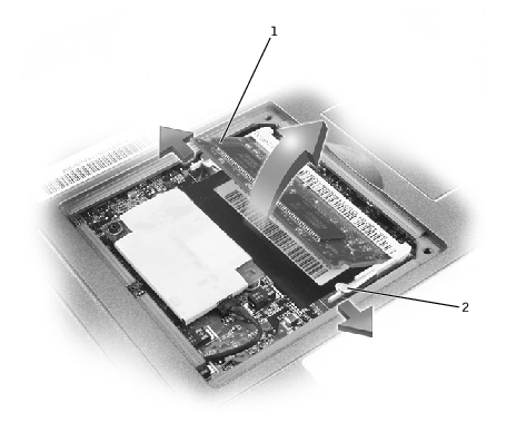
1 | memory module socket |
2 | inner tabs (2) |
|
NOTE: Memory modules are keyed, or designed to fit into their sockets, in only one direction. |
|
NOTICE: The memory module must be inserted at a 45-degree angle to avoid damaging the connector. |
|
NOTICE: Disconnect the computer and any attached devices from electrical outlets, and remove the battery. |
|
NOTICE: To avoid ESD, ground yourself by using a wrist grounding strap or by touching an unpainted metal surface on the computer. |
|
NOTICE: Read "Preparing to Work Inside the Computer" before performing the following procedure. |
|
NOTICE: Do not pull on the modem cable. Pull from the modem connector to disconnect the cable. |
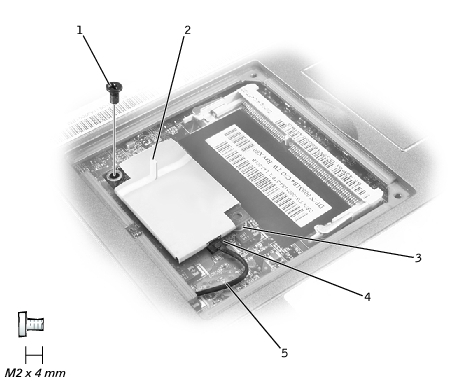
1 | M2 x 4-mm screw (1) |
2 | pull tab |
3 | boss |
4 | modem connector |
5 | modem cable |
|
NOTICE: The connectors are keyed for correct insertion; do not force the connections. |