Back to Contents Page
Dell™ Latitude™ C400
Service Manual
 Preparing to Work Inside the Computer
Recommended Tools
Screw Identification
 |
NOTICE: Only a certified service technician should perform repairs on your
computer. Damage due to servicing that is not authorized by Dell is not covered
by your warranty.
|
|
NOTICE: To avoid damaging the computer, perform the following steps before
you begin working inside the computer.
|
- Make sure that the work surface is clean to prevent scratching the
computer cover.
- Save any work in progress and close all open application programs.
- Turn off the computer and all attached devices.
 |
NOTE: Make sure the computer is turned off and not in suspend-to-disk
or hibernate mode. If you cannot shut down the computer using the
computer's operating system, press and hold the power button for 4
seconds.
|
- Make sure the computer is undocked.
- Disconnect the computer from the electrical outlet.
- To avoid possible damage to the system board, wait 10 to 20 seconds
and then disconnect any attached devices.
- Disconnect all other external cables from the computer, including the
IDE modular bay cable (if connected).
- Remove any installed PC Cards or plastic blanks from the PC Card
slot.
- Close the display and turn the computer upside down on a flat work
surface.
|
NOTICE: To avoid damaging the system board, you must remove the battery
before you service the computer.
|
- Remove the battery from the battery bay.
- To dissipate any static electricity while you work, use a wrist grounding
strap or periodically touch an unpainted metal surface.
- Handle components and cards with care. Do not touch the
components or contacts on a card. Hold a card by it edges or by its
metal mounting bracket. Hold internal components by their edges, not
by their pins.
The procedures in this manual require the following tools:
- #1 magnetized Phillips screwdriver
- Small flat-blade screwdriver
- 5-mm nut driver
- 7-mm nut driver
- Needle-nose pliers
- Flash BIOS update program floppy disk or CD
Computer Orientation
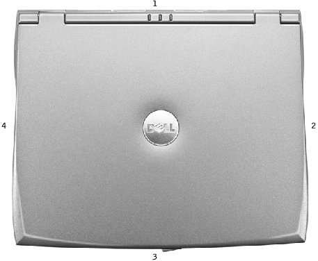
1 | back |
2 | right |
3 | front |
4 | left |
When you are removing and replacing components, photocopy the placemat as a tool to lay out and keep track of the screws. The placemat provides the number of screws and their sizes.
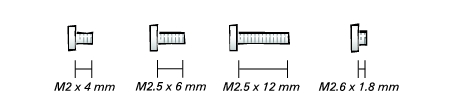
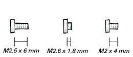
Screw Identification
|
NOTICE: When reinstalling a screw, you must use a screw of the correct
diameter and length. Make sure that the screw is properly aligned with its
corresponding hole, and avoid overtightening.
|
Hard Drive Door: (1 each) 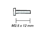
| Modem Daughter Card: (1 each) 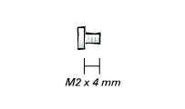
|
Keyboard: (4 each) 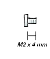
| Display Assembly: 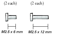
|
Display Bezel: (6 each) 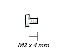
Rubber screw covers: 6 each | Palm Rest to Bottom Case: 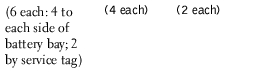
|
Critical Component Shield: (6 each) 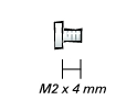
| Palm Rest to System Board: (6 each) 
|
Cooling Fan: (3 each) 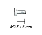
| Audio Board: (2 each) 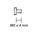
|
System Board: (1 each) 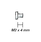
Guide pins: 2 each
5-mm hex nuts: 4 each
7-mm hex nuts: 2 each | |
Back to Contents Page