 Removing the Palm Rest
Dell™ Latitude™ C400 Service Manual
 |
NOTICE: Disconnect the computer and any attached devices from electrical outlets, and remove any installed batteries. |
|
NOTICE: To avoid ESD, ground yourself by using a wrist grounding strap or by touching an unpainted metal surface on the computer. |
|
NOTICE: Read "Preparing to Work Inside the Computer" before performing the following procedure. |
|
NOTICE: You must remove the display assembly before you remove the palm rest; the display hinges pass through the back of the palm rest. |
Palm-Rest Screws on Bottom of Computer
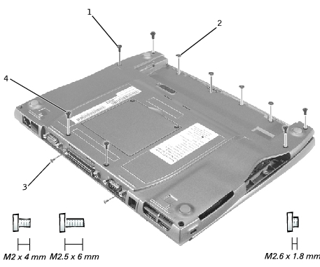
1 | M2.5 x 6-mm screws (4) |
2 | M2.6 x 1.8-mm screws (4) |
3 | M2 x 4-mm screws (2) |
4 | M2.5 x 6-mm screws (2) |
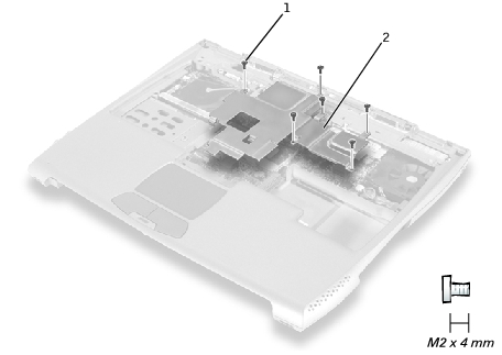
1 | M2 x 4-mm screws (6) (one screw may be captive) |
2 | critical component shield |
 |
NOTE: At this point, the memory module under the critical component shield can be replaced. |
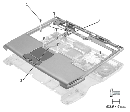
1 | M2.5 x 6-mm screws (6) |
2 | LED cable |
3 | palm-rest flex cable |
To aid with proper flex cable connection, a white locator line has been added near the ends of the flex cables. When replacing the LED and palm-rest flex cables, press the cable into the connector until the white line disappears and hold it steady while you snap the flex cable connector down. (The white line may reappear after the connector is closed; this should not indicate a problem with the connection.)