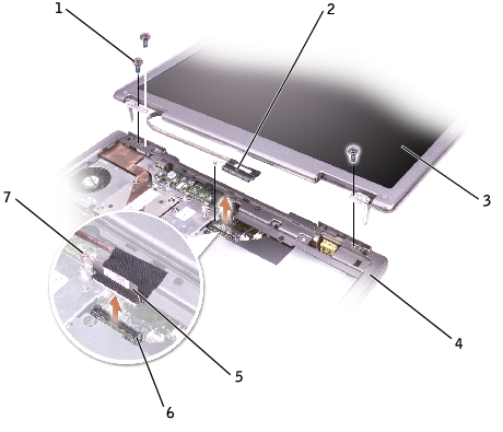
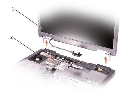
Back to Contents Page

Display Assembly and Display Latch

Dell™ Inspiron™ 600m Service Manual

  Display Assembly

  Display Bezel

  Display Panel

  Display Latch


Display Assembly

CAUTION: Before performing the following procedures, read the safety instructions in your Owner's Manual.
NOTICE: To avoid electrostatic discharge, ground yourself by using a wrist grounding strap or by periodically touching an unpainted metal surface (such as the back panel) on the computer.
NOTICE: You must remove the display assembly before you remove the palm rest.
  1. Follow the instructions in "Preparing to Work Inside the Computer."

  2. Remove the keyboard.

  3. Open the display assembly approximately 180 degrees, and support the display assembly so that it does not open past this position.

  4. Loosen the captive screw that secures the display cable to the system board, and release the cable from the four cable-routing clips.

1

M2.5 x 6-mm screws (3)

2

display cable connector

3

display

4

computer base

5

pull-tab

6

connector

7

captive screw

  1. Pull up on the pull-tab that is attached to the display cable connector to remove the connector from the system board.

  2. Remove the three M2.5 x 6-mm screws.

  3. Rotate the display assembly to a 90-degree angle, and lift the display assembly up and out of the computer base.

1

display

2

computer base

1

display bumpers (6)

5

top cover

2

M2 x 5-mm screws (6)

6

M2 x 5-mm screws (4)

3

display bezel

7

flex cable connector

4

display panel

8

flex-cable retention bracket


Display Bezel

CAUTION: Before performing the following procedures, read the safety instructions in your Owner's Manual.
NOTICE: To avoid electrostatic discharge, ground yourself by using a wrist grounding strap or by periodically touching an unpainted metal surface (such as the back panel) on the computer.
  1. Follow the instructions in "Preparing to Work Inside the Computer."

  2. Remove the keyboard.

  3. Remove the display assembly.

  4. Use a plastic scribe to pry the six display bumpers out of the screw holes located on the front of the bezel.

  5. Remove the six M2 x 5-mm screws located on the front of the bezel.

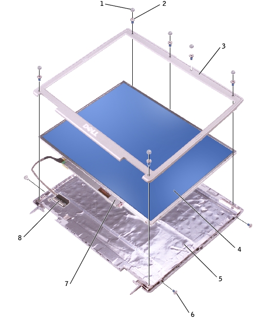
NOTICE: Carefully separate the bezel from the top cover to avoid damage to the bezel.
  1. Starting at the bottom of the display panel (by the Dell™ logo), use your fingers to separate the bezel from the top cover by lifting the inside edge of the bezel away from the top cover.


Display Panel

CAUTION: Before performing the following procedures, read the safety instructions in your Owner's Manual.
NOTICE: To avoid electrostatic discharge, ground yourself by using a wrist grounding strap or by touching an unpainted metal surface on the computer.
  1. Follow the instructions in "Preparing to Work Inside the Computer."

  2. Remove the keyboard.

  3. Remove the display bezel.

  4. Remove the two M2 x 5-mm screws from each side of the display panel.

  5. Unsnap the cable from the top cover hook, and lift the bracket out of the display assembly.

  6. Lift the display panel, and rotate the display panel out of the top cover.

  7. Use the pull-tab to disconnect the bottom flex-cable connector from the inverter connector.

1

top flex-cable connector

2

top display-cable connector

3

pull-tab on bottom flex-cable connector

  1. Press in both sides of the top display cable connector, and pull the display cable connector away from the top flex-cable connector.


Display Latch

NOTICE: Disconnect the computer and any attached devices from electrical outlets, and remove any installed batteries.
NOTICE: To avoid electrostatic discharge, ground yourself by using a wrist grounding strap or by touching an unpainted metal surface on the computer.
  1. Remove the keyboard.

  2. Remove the display assembly.

  3. Remove the display bezel.

  4. Remove the two M2 x 5-mm screws that secure the display bracket to the top cover.

  5. Lift the display bracket out of the top cover, and then remove the display latch.

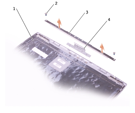
NOTE: Ensure that the display bracket is upright when you replace the display latch.

1

top cover

2

M2 x 5-mm screws (2)

3

display bracket

4

display latch


Back to Contents Page