Return to MAIN-Index  Return to SUB-Index    IBM-AUSTRIA - PC-HW-Support    30 Aug 1999

The ServeRAID Configuration Program Screens


The ServeRAID Configuration Program Screens

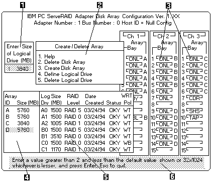
Use the IBM ServeRAID configuration program on the Array Configuration (also called the ServeRAID Configuration) diskette to configure or view the disk array. The following example screen is a compilation of many of the IBM ServeRAID Controller Disk Array Configuration (also called the ServeRAID Configuration program) screens. The list that follows example, explains the numbered areas of the example.
 
  1.  This area displays pop-ups that apply to the current menu. For example, a pop-up allows you to  select the logical drive size by entering the size in megabytes, or, to accept the default value shown.
     Another pop-up allows you to select the RAID level you want to assign to the logical drive you are defining. When  you need to confirm an action, the Confirm pop-up appears in this area.
  2.  You can select any of the choices that appear on the menus.
  3.  The Bay/Array selection list  shows 15 bays for each of the adapter's three channels.  For each bay that contains a drive, the list indicates the state of the physical drive and the array in which the drive is grouped.  For example, in the illustration, the drive in Channel 2 Bay 1, has a drive status of ONL and is a part of Array B. Selections are  made from this list to determine which bays (hard disk drives) are in the arrays.

    Note:

    1.  The Bay/Array area on the screen does not reflect the physical  configuration of the server. In the server, the default numbering for the hard disk drive bays in each bank is  1 through 6 (from left to right from top to bottom).
    2.  The IDs for the hot-swappable drives are set by the backplanes.. This allows you to  define the IDs as low (0 to 5) or high (8 to 13)
       Refer to the 'Backplane Information'
    3.  One channel on the ServeRAID adapter can support two daisy-chained banks of bays.  The SCSI ID jumpers on the backplanes must be set to avoid SCSI ID conflicts.
    4.  The Bay Number correspondeds to the SCSI ID on the device plus 1. When the SCSI IDs are  set to high, the hard disk drive with SCSI ID 8 is installed in the leftmost bay, its status displays in Bay Number 9.

  4.  The Array list indicates the array ID and the size (in megabytes) of the array. When a drive is being rebult, this area, along  with the Logical Drive list area, shows the progression of the rebuilding process.
  5.  The Logical Drive list identifies the logical drive (for example, A1), including its size, the RAID level, date of creation, and its write policy.

     The status of the logical drive also is shown.

    OKY No problem conditions are associated with the drive.
    CRT Replace the defunct drive and do a rebuild operation.
      (you will have received a message telling you what has happened to the drive).
    OFL The logical drive is irrecoverable, the data in that drive is lost.

     When a drive is being rebuilt, this area, along with the Logical  Drive list area,  shows the progression of the rebuilding process.

     During an initialization process, the Write Policy area displays the percent initialized, during a synchronization process, it displays the percent synchronized.

  6.  The information areas tells you the action you can perform on this screen or pop-up.


Back to  Jump to TOP-of-PAGE
More INFORMATION / HELP is available at the  IBM-HelpCenter

Please see the LEGAL  -  Trademark notice.
Feel free - send a Email-NOTE  for any BUG on this page found - Thank you.