|
|
 Narrow/Wide Hot Swap Tray III Option (Installation)
Backplane III FRU PN (06H8629) 76H2671
BackPlane III OPT PN (70G9855) 76H2670 UPOS SHSBP3Y
-------------------------------------------------------------------
RAID Hot Swap HDD III with 2x LED + button ZG96-0121
Prerequ. 'AUTOBAHN'- type III Backplane or 3517 - 3518
Option with Harddisk.
HDD and Tray 1.12GB 2.25GB 4.5(5.0)GB
------------------|-------------|-------------|---------- OPTION --
Tray UPOS-P/N | S1GHS2Y | S2GHS2Y | S4GHS2Y
Mfg. P/N | 70G9861 1.) | 70G9862 1.) | 70G9863
-------------------------------------------------------------------
Note 1 see > ECA012
--------------------------------------------------------- FRU P/N -
Drive Tray III | 06H8631 | 06H8631 | 06H8631
incl. SCSI 16-bit cable and LED/button cable, but w/o ID cable
------------------|-------------|-------------|--------------------
Backplane to | 06H8644 | 06H8644 | 06H8644
Backplane Data Cable 200mm (8.5 - Inch) |
------------------|-------------|-------------|--------------------
SCSI ID Cable | 06H8664 | 06H7691 | 06H7691
------------------|-------------|-------------|--------------------
LED/button cable | 07H1696 | 07H1696 | 07H1696
------------------|-------------|-------------|--------------------
Harddisk | 06H8560 | 42H1821 | 76H0959
| | 76H0958 |
------------------|-------------|-------------|--------------------
Screw (qty. 4) | 1147429 | 1147429 | 1147429
-------------------------------------------------------------------


| Jumper Position | Description |
|---|---|
| E | Address for a backplane installed in Bank E |
| D | Address for a backplane installed in Bank D |
| C | Address for a backplane installed in Bank C |
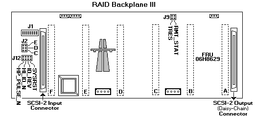
Setting Backplane III - SCSI ID Jumpers - J12
The SCSI ID address jumper, a pin block with four pairs of pins (J12),
is located on the rear of the backplanes in banks C, D and E. When two backplanes are daisy chained
in your server or expansion enclosure, the first backplane address jumper (for example, Bank C) must be set to LOW , defining
the SCSI IDs as 0 through 5. The second backplane (in this example, bank D), must be set to either HI or Reverse ,
defining the SCSI IDs as 5 through 0, or HI, defining the SCSI IDs as 8 to D. The default, no jumper installed, is to set the addresses LO.
If the SCSI adapter supports more than eight SCSI devices per SCSI channel, the second backplane can be set to either HI or Reverse.
However, if the SCSI Adapter supports eight or fewer SCSI devices per SCSI channel, the second backplane must be set to Reverse.
Jumper Position Description
----------------------------------------------------------------
2 4 6 8
J12 ° ° ° ° LO Sets SCSI IDs to LO, starting from SCSI
° ° ° ° ID 0 (bay 1) to SCSI ID 5 (bay 6)
1 3 5 7 (No jumper required)
----------------------------------------------------------------
2 4 6 8
J12 ° ° | ° LO Sets SCSI IDs to LO and Reverse,
° ° | ° starting from SCSI ID 5 (bay 1)
1 3 5 7 to SCSI ID 0 (bay 6)
----------------------------------------------------------------
2 4 6 8
J12 ° | ° ° HI Sets SCSI IDs to HI, starting from SCSI
° | ° ° ID 8 (bay 1) to SCSI ID D (bay 6)
1 3 5 7
Please see the LEGAL - Trademark notice.
Feel free - send a  for any BUG on this page found - Thank you.