 |

 IBM-AUSTRIA - PC-HW-Support 30 Aug 1999
 |
Installing the Processor Housing
Installing the Processor Housing
Complete this procedure to install the processor housing.
- If slot 6 contains an adapter, move the adapter to an empty slot.
If slot 5 contains a full-size adapter, move the adapter to an empty slot.
(Only half-size adapters will fit in slot 5.)
- Remove the slot 5 and 6 plastic guides opposite the bulkhead.
- If you have installed the SCSI Controller-to-Bulkhead
Cable option, remove the option and replace it with
the SCSI controller-to-bulkhead cable contained in this option:
- Detach the SCSI cable from the SCSI connector on the system board.
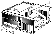
- Remove the screws from the external connector on the bulkhead opening.
- Connect one end of the SCSI cable contained in
this option to the SCSI connector on the system board.
- Insert the SCSI cable external connector 1 into the knockout opening.
- Insert the two screws 2 that come with the
replacement SCSI cable into the external connector; tighten the screws.
- Optionally, install the RS-485 cable:
Note:
Only models with either 01K7234 or 28L1019 as
the system board assembly part number support
the RS-485 cable option. The system board
assembly part number is located near the battery
on the system board.
- Connect the RS-485 cable to the RS-485
connector (J27) 2 on the system board.
- Insert the external connector into the knockout opening 1.
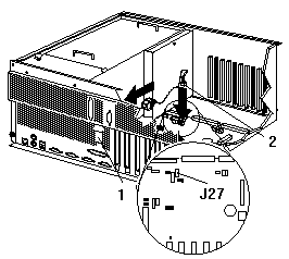
- Install the jumper extension cable on the Power on control jumper (J32):
- Note the position of the jumper on the pin block and remove the jumper.
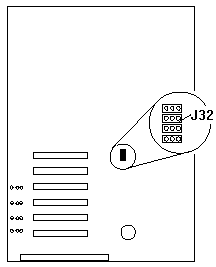
- Align the white cable with pin 1 and insert the connector over the pin block.
- If necessary, change the position of the jumper
on the jumper extension cable.
Note:
The default jumper position of J32 and the
jumper extension cable is a jumper on pins 1 and 2. Refer to the 'Hardware
Information' section of the IBM Netfinity
5500 M20 Server Library for a description of the jumper.
- Route the jumper extension cable along the system board and the shuttle side wall.
- Replace the processor housing guide:
- Remove the screws that secure the processor housing guide and remove the guide.
- Install the processor housing guide 1 that
comes with this option and secure with screws 2.
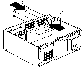
- Replace the fan assembly and press on the fasteners to lock in place.
- Replace the processor housing top cover and press
on the fasteners to lock in place.
- Align the shuttle with the guides and slide the shuttle
partially into the server.
- Reconnect the cables to the shuttle that you disconnected in step 14 of
Removing the Shuttle and Processor Housing.
- Reconnect the power cables that you disconnected in step 3 of
Removing the Shuttle and Processor Housing.
- Grasp the handles on the processor housing top cover and lift the housing.
- Orient the processor housing with the cable
connectors toward the front of the server.
 - Attention: -
When you install the processor housing in the server,
be sure that it is aligned correctly before seating in the shuttle.
Incorrect seating might cause damage to server components.
- Align the processor housing with the guides.
Carefully lower the processor housing into the shuttle until it is fully seated.
- Install and tighten the four blue thumbscrews.
- Install the half-card slot insulator between slot 5 and the processor housing.
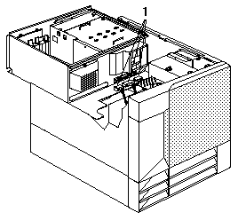
- Connect the power supply cables 1 to the processor housing.
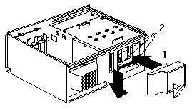
- Secure the air diffuser 1 in the server by positioning
the air diffuser on the matching metal tabs 2 on the shuttle.
- Seat the shuttle in the server and tighten the four shuttle thumbscrews.
- Place the IBM Netfinity 5500 M20 system service
label on the inside of the top cover.
- Place one upgrade sticker near the machine type
serial number on the information label. The upgrade
sticker identifies the server as having this option installed.
Note:
The information label is located at the front of the
server behind the media-bay trim bezel.
- Place the other upgrade sticker on the front bezel,
above the machine type serial number.
- Place the Intel® microprocessor label on the front bezel.
- Reinstall the top cover.
- Check that all cables, adapters, and other
components are installed and seated correctly
and that you have not left loose tools or parts inside the server.
- Lower the cover with the rear edge of the cover
approximately 2.5 cm (1 in.) back from the rear edge of the server.
- Slide the cover forward.
- Tighten the two thumbscrews on the back edge of the cover.
- Go to Completing the Upgrade Installation.
Back to 
More INFORMATION / HELP is available at the IBM-HelpCenter
Please see the LEGAL - Trademark notice.
Feel free - send a  for any BUG on this page found - Thank you.


 - Attention: -
When you install the processor housing in the server,
be sure that it is aligned correctly before seating in the shuttle.
Incorrect seating might cause damage to server components.


 for any BUG on this page found - Thank you.