 |

 IBM-AUSTRIA - PC-HW-Support 30 Aug 1999
 |
Installing memory-modules
Installing memory-modules
You install memory-modules on the memory board
included in the Processor Upgrade Kit.
Notes:
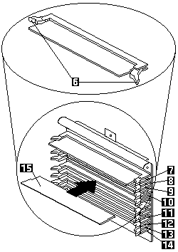
- Install memory modules in connectors J1, J5, J2, J6,
J3, J7, J4, and J8, in that order. (See the illustration
below for memory connector locations.)
- If you mix DIMM sizes, install the largest sized DIMM
in connector J1, the next largest sized DIMM in
connector J2, and so forth, to enhance memory-module performance.
- Installing or removing memory modules changes the configuration
information in the server. Therefore, after installing or removing a DIMM,
you must save the new configuration information in the Configuration/Setup
program. When you restart the server, the system displays a message indicating
that the memory configuration has changed. Start the
Configuration/Setup Utility program and select Save Settings.
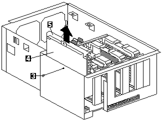
Refer to the following illustrations of the processor housing
and the processor board while you perform the steps in this procedure.

3 Thumbscrew
4 Memory board
5 Memory board handle

6 Retaining clips
7 Memory connector 1 (J1)
8 Memory connector 2 (J2)
9 Memory connector 3 (J3)
10 Memory connector 4 (J4)
11 Memory connector 5 (J5)
12 Memory connector 6 (J6)
13 Memory connector 7 (J7)
14 Memory connector 8 (J8)
15 DIMM
Complete this procedure to install memory-modules.
- Remove the memory board:
- Remove the thumbscrew 3 from the side of the processor housing.
- Lift up on the memory board handle 5 and
remove the memory board 4 from the server.
- Place the memory board on a static-protective
surface, such as the static-protective package in which the option came.
- Locate the memory-module connectors on the
memory board. Determine the memory-module
connector into which you will install the memory module.
- Touch the static-protective package containing the
memory-module kit to any unpainted metal surface on
the server. Then, remove the memory module from the package.
Note:
To avoid breaking the retaining clips or damaging
the memory-module connectors, handle the clips gently.
- Install the memory module:
- Turn the memory module (DIMM) 15 so that
the pins align correctly with the connector 7.
- Insert the DIMM into the connector by pressing
on one edge of the DIMM and then on the other
edge of the DIMM. Be sure to press straight into
the connector. The retaining clips 6 will snap
into the closed positions.
- Make sure the retaining clips 6 are in the
closed position. If a gap exists between the
DIMM and the retaining clips, the DIMM has not
been properly installed. In this case, open the
retaining clips and remove the DIMM; then, reinsert the DIMM.
- Repeat these steps for each memory module that you install.
- Install the memory board:
- Hold the memory board by the top edge and
align the memory board over the memory board connector.
- Press on the top edge of the memory board,
insert the memory board into the connector, and
tighten the thumbscrew to secure.
- Go to Installing the processor Housing.
Back to 
More INFORMATION / HELP is available at the IBM-HelpCenter
Please see the LEGAL - Trademark notice.
Feel free - send a  for any BUG on this page found - Thank you.


 for any BUG on this page found - Thank you.