|
|
| Pins | Description |
|---|---|
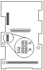
| 1-2 (A0) | Removing the jumper from these two pins reverses the SCSI IDs on the backplane. For the tower model, these two pins are jumpered, for the rack model, the jumper usually is removed. |
| 3-4 (A1) | Reserved. No jumper. |
| 5-6 (A2) | These pins are always jumpered. |

| J4 Pins 1-2 (A0) | Bay 1 | Bay 2 | Bay 3 | Bay 4 | Bay 5 |
|---|---|---|---|---|---|
| Jumpered (tower orientation) | 0 | 1 | 2 | 3 | 4 |
| Jumper removed, DASD enclosure not rotated. |
4 | 3 | 2 | 1 | 0 |
| Jumper removed, DASD enclosure rotated for rack orientation. |
0 | 1 | 2 | 3 | 4 |
Notes: When the DASD enclosure on a tower model has been rotated
for rack-mount orientation and the jumper has been removed, the bays
correspond to the rack model illustration.
DASD Backplane Jumper Block Location: The following illustration shows the location of the DASD
backplane SCSI option jumper block (J4).

Please see the LEGAL - Trademark notice.
Feel free - send a  for any BUG on this page found - Thank you.