 |

 IBM-AUSTRIA - PC-HW-Support 30 Aug 1999
 |
Adapter Installation (Netfinity 7000 - 8651)
Adapter Installation

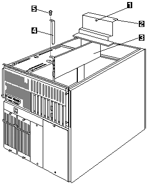
- Captive screw
- Adapter support panel
- Adapter
- Expansion slot cover
- Expansion slot screw
To install an adapter:
- Power-off the server and peripheral devices and
disconnect all external cables and power cords, then,
remove the top cover (see 'Cover (Top)').
- Remove the adapter-support panel -2- by loosening
the screw -1- and lifting the panel out of the server.
- Determine which expansion slot you will use for the adapter.
NOTE: Check the instructions that come with the adapter
for any requirements or restrictions
- Remove the expansion slot cover -4-
- Remove the screw -5- on the top of the expansion-slot cover -4-
- Slide the expansion-slot cover out of the server.
- Store these items in a safe place for future use.
 Expansion-slot covers must be installed on
all vacant slots. This maintains the electromagnetic emissions characteristics of
the system and ensures proper cooling of system components.
- Place the adapter, component-side up, on a flat,
static-protective surface.
- Set any jumpers or switches as described by the
adapter manufacturer.
- Refer to the documentation that comes with the
adapter for any cabling instructions. It might be
easier for you to route any cables before you install the adapter.
- Install the adapter:
- Carefully grasp the adapter El by its top edge
or upper corners, and align it with the expansion
slot on the system (planar) board.
 Be careful not to damage the EMC gasket
when you install the adapter.
- Press the adapter firmly into the expansion slot.
The tapered foot of the adapter-retaining bracket
must fit info the mating slot in the expansion-slot frame.
 When you install an adapter in the server,
be sure that it is completely and correctly
seated in the system-board connector before
you apply power. Incomplete insertion might
cause damage to the system (planar) board or the adapter.
- Align the rounded notch in the retaining bracket
with the threaded hole in the expansion-slot
frame. The retaining bracket on the adapter fits
into the space that was occupied by the
expansion-slot cover.
- Insert the expansion-slot screw a that you
removed earlier into the threaded hole, and push
the rounded notch up against the screw.
- Tighten the expansion-slot screw firmly.
- Connect any needed cables to the adapter.
- Reinstall the adapter-support bracket -2- and tighten the screw -1-
Back to 
More INFORMATION / HELP is available at the IBM-HelpCenter
Please see the LEGAL - Trademark notice.
Feel free - send a  for any BUG on this page found - Thank you.

 Expansion-slot covers must be installed on
all vacant slots. This maintains the electromagnetic emissions characteristics of
the system and ensures proper cooling of system components.
 Be careful not to damage the EMC gasket
when you install the adapter.
 When you install an adapter in the server,
be sure that it is completely and correctly
seated in the system-board connector before
you apply power. Incomplete insertion might
cause damage to the system (planar) board or the adapter.
 for any BUG on this page found - Thank you.