Dell™ Latitude™ C810 Service Manual
 |
NOTICE: Only a certified service technician should perform repairs on your computer. Damage due to servicing that is not authorized by Dell is not covered by your warranty. |
|
NOTICE: Unless otherwise noted, each procedure in this manual assumes that a part can be replaced by performing the removal procedure in reverse order. |
|
NOTICE: Disconnect the computer and attached devices from the electrical outlet and remove any installed batteries. |
|
NOTICE: To avoid ESD, ground yourself by using a wrist grounding strap or by periodically touching unpainted metal on the computer. |
|
NOTICE: The hard drive is very sensitive to shock. Handle it by its edges (do not squeeze the top of the case), and avoid dropping it. |
|
NOTICE: Disconnect the computer and attached devices from the electrical outlet and remove any installed batteries. |
|
NOTICE: To avoid ESD, ground yourself by using a wrist grounding strap or by periodically touching unpainted metal on the computer. |
|
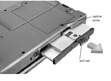
NOTICE: To keep the pull tab from catching on the captive screw, turn the computer over before removing the fixed optical drive. |
|
NOTICE: Disconnect the computer and any attached devices from electrical outlets and remove any installed batteries. |
|
NOTICE: To avoid ESD, ground yourself by using a wrist grounding strap or by periodically touching unpainted metal on the computer. |

 |
NOTE: Memory modules are keyed to fit into their sockets in only one direction. |
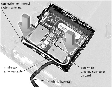
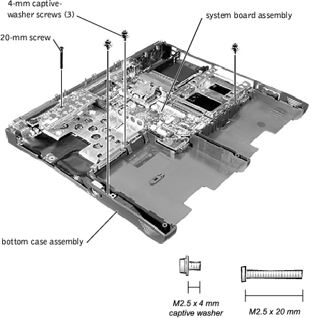
You must remove the optional Mini PCI Card assembly before the system board assembly can be removed. A Mini PCI Card assembly may consist of a modem, a NIC, a modem and NIC combination, or a wireless NIC. A modem, NIC, or modem and NIC combination must be connected to the wiring harness as appropriate; a wireless NIC must be connected to the system's internal antenna.
|
NOTICE: Disconnect the computer and attached devices from electrical outlets and remove any installed batteries. |
|
NOTICE: To avoid ESD, ground yourself by using a wrist grounding strap or by periodically touching unpainted metal on the computer. |
|
NOTICE: The connectors are keyed for correct insertion; do not force the connections. |
Mini PCI Card Assembly Using Wiring Harness

Mini-PCI Wireless NIC Assembly Using Antenna Cable
|
NOTICE: If a wireless NIC card contains two mini-coax antenna connectors, connect the mini-coax antenna cable to the outermost antenna connector on the card as shown. |
|
NOTICE: If you are installing a wireless NIC, fold and tuck the unused wiring harness into the slot so it does not interfere with the cover. |
|
NOTICE: Disconnect the computer and attached devices from electrical outlets and remove any installed batteries. |
|
NOTICE: To avoid ESD, ground yourself by using a wrist grounding strap or by periodically touching unpainted metal on the computer. |
|
NOTICE: Be careful when handling the keyboard. The keycaps are fragile, easily dislodged, and time-consuming to replace. |

|
NOTICE: Position the keyboard/track stick flex cable so it is not pinched when you replace the keyboard in the bottom case assembly. |
|
NOTICE: Disconnect the computer and attached devices from electrical outlets and remove any installed batteries. |
|
NOTICE: To avoid ESD, ground yourself by using a wrist grounding strap or by periodically touching unpainted metal on the computer. |

|
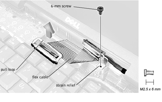
NOTICE: Make sure you remove the flex cable before you remove the display assembly. |
|
NOTICE: When reconnecting the flex cable, press down on both ends of the connector, not in the middle. Pressing the middle of the connector can damage fragile components. |
Display Assembly Bezel and Panel
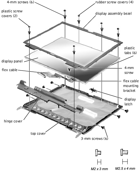
The bezel is secured to the display assembly top cover with plastic tabs around the sides. Use a plastic scribe to help separate the bezel from the top cover.
Flex Cable Connectors on Display Panel

|
NOTE: Use a magnetic screwdriver to reassemble the display panel in the display. |
|
NOTICE: Disconnect the computer and attached devices from electrical outlets and remove any installed batteries. |
|
NOTICE: To avoid ESD, ground yourself by using a wrist grounding strap or by periodically touching unpainted metal on the computer. |

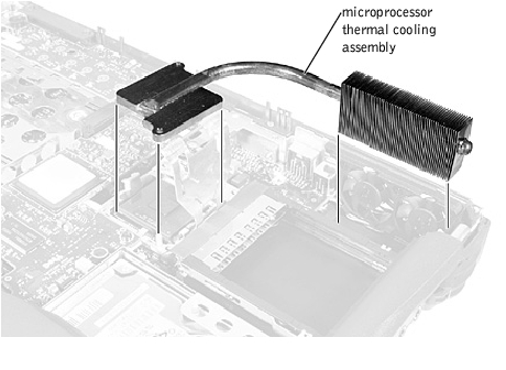
Microprocessor Thermal Cooling Assembly
|
NOTICE: To ensure maximum cooling for the microprocessor, do not touch the heat transfer areas on the microprocessor thermal cooling assembly. The oils in your skin reduce the heat transfer capability of the thermal pads. |
|
NOTICE: Disconnect the computer and attached devices from electrical outlets and remove any installed batteries. |
|
NOTICE: To avoid ESD, ground yourself by using a wrist grounding strap or by periodically touching unpainted metal on the computer. |

|
NOTICE: To ensure maximum cooling for the microprocessor, do not touch the heat transfer areas on the thermal cooling assembly. The oils in your skin reduce the heat transfer capability of the thermal pads. |
|
NOTICE: When removing the microprocessor module, pull the module straight up. Do not bend the pins. |
|
NOTICE: To avoid damage to the microprocessor, hold the screwdriver so that it is perpendicular to the microprocessor when removing the cam lock screw (see "Microprocessor Cam Lock Screw"). |
Microprocessor Cam Lock Screw (Example)
|
NOTICE: Hold the microprocessor down while turning the cam lock screw to prevent intermittent contact between the cam lock screw and microprocessor. |

|
NOTICE: If you received a flash BIOS update program diskette or CD with the replacement microprocessor, you must update the BIOS after replacing the microprocessor module. For instructions on updating or reflashing the BIOS, see the Dell Portable Computer BIOS Update Guide. |
|
NOTICE: Proper seating of the microprocessor module does not require force. |
|
NOTICE: A microprocessor module that is not properly seated can result in an intermittent connection and subsequent failures. |
When the microprocessor module is correctly seated, all four corners are aligned to the same height. If one or more corners of the module are higher than the others, the module is not seated correctly.
|
NOTICE: Hold the microprocessor down while turning the cam lock screw to prevent intermittent contact between the cam lock screw and microprocessor (see "Microprocessor Cam Lock Screw"). |
|
NOTICE: Do not over- or undertighten the screw. Tighten it until the screw indicator points to the "closed" or "locked" indicator on the socket. |
Closing the Microprocessor Retaining Clip

|
NOTICE: Disconnect the computer and attached devices from electrical outlets and remove any installed batteries. |
|
NOTICE: To avoid ESD, ground yourself by using a wrist grounding strap or by periodically touching unpainted metal on the computer. |
|
NOTICE: Make sure the board is correctly and firmly seated before continuing. Failure to do so will cause intermittent video failures. |
|
NOTICE: Disconnect the computer and attached devices from electrical outlets and remove any installed batteries. |
|
NOTICE: To avoid ESD, ground yourself by using a wrist grounding strap or by periodically touching unpainted metal on the computer. |
|
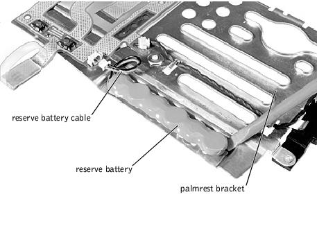
NOTICE: The reserve battery provides power to the computer's time RTC and NVRAM when the computer is turned off. Removing the palmrest disconnects the reserve battery and causes the computer to lose the date and time information as well as all user-specified parameters in NVRAM. If possible, make a copy of this information before you disconnect the reserve battery. |
|
NOTICE: To avoid damaging the palmrest assembly, you must first remove the display assembly. |
|
NOTICE: Disconnect the computer and attached devices from electrical outlets and remove any installed batteries. |
|
NOTICE: To avoid ESD, ground yourself by using a wrist grounding strap or by periodically touching unpainted metal on the computer. |
|
NOTICE: The reserve battery provides power to the computer's RTC and NVRAM when the computer is turned off. Removing the battery causes the computer to lose the date and time information as well as all user-specified parameters in NVRAM. If possible, make a copy of this information before you remove the reserve battery. |
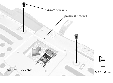
Palmrest Flex Cable and Bracket
|
NOTICE: Disconnect the computer and attached devices from electrical outlets and remove any installed batteries. |
|
NOTICE: To avoid ESD, ground yourself by using a wrist grounding strap or by periodically touching unpainted metal on the computer. |
The system board's BIOS chip contains the system service tag number, which is also visible on a bar-code label on the bottom of the computer.
The replacement kit for the system board assembly includes a diskette or CD that provides a utility for transferring the service tag number to the replacement system board assembly.
|
NOTICE: If you received a flash BIOS update program diskette or CD with the replacement microprocessor, you must update the BIOS after replacing the microprocessor module. For instructions on updating or reflashing the BIOS, see the Dell Portable Computer BIOS Update Guide. |
|
NOTICE: Disconnect the computer and attached devices from electrical outlets and remove any installed batteries. |
|
NOTICE: To avoid ESD, ground yourself by using a wrist grounding strap or by periodically touching unpainted metal on the computer. |
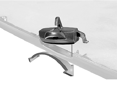
Battery and Modular Bay Latch Assemblies
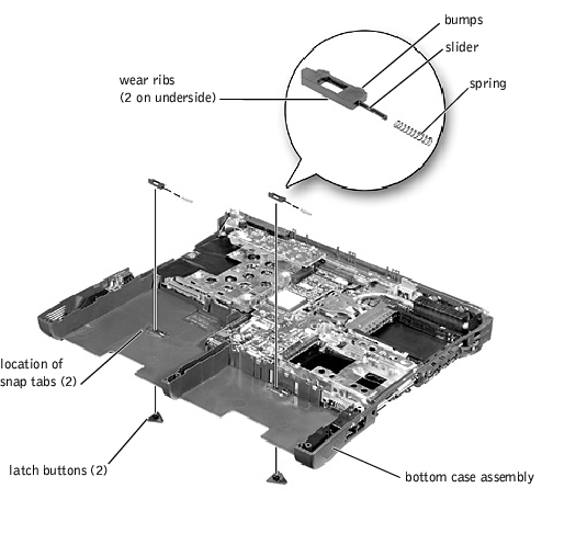
Apply downward pressure to the tabs while squeezing them together (tweezers work well) to eject the latch button from the bottom of the case without loosening the upper latch assembly (spring and slider). If the upper latch assembly does come loose:
|
NOTICE: Disconnect the computer and attached devices from electrical outlets and remove any installed batteries. |
|
NOTICE: To avoid ESD, ground yourself by using a wrist grounding strap or by periodically touching unpainted metal on the computer. |
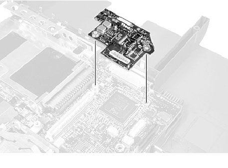
Align the screw holes on the battery charger board with the screw holes on the bottom case assembly (see Battery Charger Board), and then press the battery charger board down into its connector.
|
NOTICE: Disconnect the computer and attached devices from electrical outlets and remove any installed batteries. |
|
NOTICE: To avoid ESD, ground yourself by using a wrist grounding strap or by periodically touching unpainted metal on the computer. |

|
NOTICE: Disconnect the computer and attached devices from electrical outlets and remove any installed batteries. |
|
NOTICE: To avoid ESD, ground yourself by using a wrist grounding strap or by periodically touching unpainted metal on the computer. |
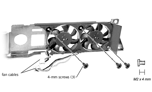
|
NOTICE: When reconnecting the fan cables, connect the shorter cable to the connector closest to the fan assembly. Route both cables so that they will not be pinched by the thermal cooling assembly. |
|
NOTICE: Disconnect the computer and attached devices from electrical outlets and remove any installed batteries. |
|
NOTICE: To avoid ESD, ground yourself by using a wrist grounding strap or by periodically touching unpainted metal on the computer. |
RJ-11 and RJ-45 Connector Covers
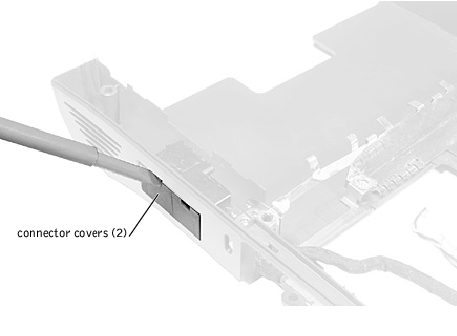
Remove a plastic connector cover (if necessary) by slipping a nonmarring tool into the cutout at the top and pivoting the tool up to disengage the inner securing tab.
To replace a connector cover, orient the cover notch-side-up and snap it into the connector cutout.
|
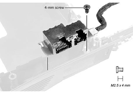
NOTICE: The plastic tab is fragile; pull it back only far enough to remove the board assembly. |
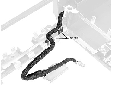
When replacing the RJ-11/RJ-45 board assembly, protect the wiring harness by routing it between the plastic posts.
RJ-11/RJ-45 Board Harness Routing