 |

 IBM-AUSTRIA - PC-HW-Support 30 Aug 1999
 |
Front Panel Control Board Interface (8650)
Front Panel Control Board Interface

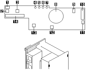
- Signal from C2 switch at back edge near card
cage
3-pin right-angle latching-style connector
- Power switch
- Reset switch
- Power-on LED, green
- Power-fail LED, amber
- Cooling-fail LED, amber
- Drive-fault LED, amber
- Speaker
- Signal from intrusion switch at back edge near power
supplies
3-pin right-angle latching-style connector
- Signal interface to the LCD
14-pin straight-head connector
- Power to the LCD
3-pin straight-head connector latching-style connector
- Hard drive bay C2 switch
- NMI switch
- Signal interface to system board
40-pin straight-head connector (pin 17 removed)
More INFORMATION / HELP is available at the IBM-HelpCenter
Please see the LEGAL - Trademark notice.
Feel free - send a  for any BUG on this page found - Thank you.

 for any BUG on this page found - Thank you.