|
|

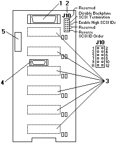
SCSI Backplane Option Jumpers
The option jumper block on the SCSI backplane defines
the SCSI IDs for hot-swap drives. See the (above) illustration for
the location of the option jumper block (J10).
Table 11 summarizes the settings for the SCSI backplane
option jumper block (J10).
The below table shows the SCSI IDs that you can use for hot-swap drives.
SCSI IDs for Hot-Swap Drives
| J10 Pins 5-6 |
J10 Pins 11-12 |
Bay 1 | Bay 2 | Bay 3 | Bay 4 | Bay 5 | Bay 6 |
|---|---|---|---|---|---|---|---|
| No jumper |
No jumper |
0 | 1 | 2 | 3 | 4 | 5 |
| No jumper |
jumper | 5 | 4 | 3 | 2 | 1 | 0 |
| jumper | No jumper |
13 | 12 | 11 | 10 | 9 | 8 |
Notes:
Please see the LEGAL - Trademark notice.
Feel free - send a  for any BUG on this page found - Thank you.