 |

 IBM-AUSTRIA - PC-HW-Support 30 Aug 1999
 |
Cabling Example for the ServeRAID Adapter (Netfinity 7000 - 8651)
Cabling Example for the ServeRAID Adapter
You can install an optional ServeRAID adapter in the server to enable you to configure the
hot-swap hard disk drives into disk arrays. The following
procedure describes the cable routing that is necessary
when you install the ServeRAID adapter.
NOTE: For ease of cabling, install the optional ServeRAID
adapter in PCI slot 1. It might be easier for you to
route the cables before you install the adapter.

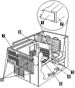
- Air baffle
- Shuttle-support rails
- Opening in shuttle
- SCSI port A
- SCSI port B
- Captive screws
- Shuttle
- Opening in shuttle
To correctly rout the ServerRAID adapter cable, do the following:
- Loosen the tour screws -6-, on the shuttle at the back
of the server.
- Pull the shuttle -7- toward the back of the server.
- Observe the way the edges of the air baffle -1- fits
inside the shuttle-support rails -2-, then, slide the air
baffle toward the rear of the server and lift it out of
the server.
- Disconnect the SCSI cable from SCSI port B -5- on
the system (planar) board.
- Slide the disconnected end of the cable out through
the opening -3- in the shuttle.
- Reroute the SCSI cable through the opening a in
the center of the shuttle.

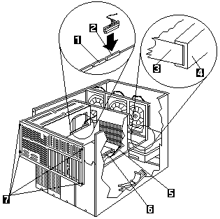
1. Channel 2
2. Channel 1
3. Air baffle
4. Shuttle-support rails
5. SCSI port A
6. SCSI port B
7. Captive screws
- It you have already installed the ServeRAID adapter,
connect the cable to Channel 2 -1- on the
ServeRAID adapter. If you have not yet installed the
ServeRAID adapter, connect the cable after you
install the adapter.
- Repeat this procedure to disconnect the SCSI cable
from SCSI port A -5- on the system (planar) board and
connect it to Channel 1 -2- on the ServeRAID
adapter.
 If the air baffle is not installed correctly, the
server will overheat.
- Install the air baffle -3-. Make certain that the edges
of the air baffle fit inside the shuttle support rails -4-.
- Push the shuttle toward the front of the server and
tighten the four screws -7- at the back of the shuttle.
Back to 
More INFORMATION / HELP is available at the IBM-HelpCenter
Please see the LEGAL - Trademark notice.
Feel free - send a  for any BUG on this page found - Thank you.


 If the air baffle is not installed correctly, the
server will overheat.
 for any BUG on this page found - Thank you.