Back to Contents Page

Before You Begin

Dell™ Latitude™ C600/C500 Series Service Manual

  Preparing to Work Inside the Computer

  Recommended Tools

  Screw Identification


Preparing to Work Inside the Computer

NOTICE: Only a certified service technician should perform repairs on your system. Damage due to servicing that is not authorized by Dell is not covered by your warranty.
NOTICE: To avoid damaging the computer, perform the following steps before you begin working inside the computer.
  1. Make sure that the work surface is clean to prevent scratching the computer cover.

  2. Save any work in progress and close all open application programs.

  3. Turn off the computer and all attached devices.

NOTE: Make sure the computer is turned off and not in suspend-to-disk or hibernate mode. If you cannot shut down the computer using the computer's operating system, press and hold the power button for 4 seconds.
  1. Make sure the computer is undocked.

  2. Disconnect the computer from the electrical outlet.

  3. To avoid possible damage to the system board, wait 10 to 20 seconds and then disconnect any attached devices.

  4. Disconnect all other external cables from the computer.

  5. Remove any installed PC Cards or plastic blanks from the PC Card slot.

  6. Close the display and turn the computer upside down on a flat work surface.

NOTICE: To avoid damaging the system board, you must remove the main battery and secondary battery (if present) before you service the computer.
  1. Remove the primary battery from the battery bay and the secondary battery from the modular bay, if a secondary battery is in use.

  2. Remove any installed device in the modular bay.

  3. To dissipate any static electricity while you work, use a wrist grounding strap or periodically touch an unpainted metal surface.

  4. Handle components and cards with care. Do not touch the components or contacts on a card. Hold a card by it edges or by its metal mounting bracket. Hold a component such as a microprocessor by its edges, not by its pins.


Recommended Tools

The procedures in this manual require the following tools:

System Orientation


Screw Identification

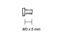
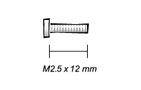
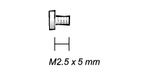
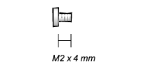
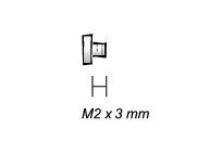
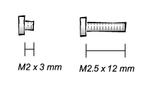
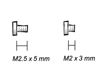
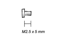
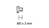
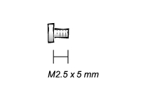
When you are removing and replacing components, photocopy the placemat as a tool to lay out and keep track of the component screws. The placemat provides the number of screws and the sizes.

Screw Identification

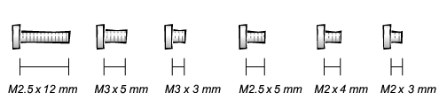
NOTICE: When reinstalling a screw, you must use a screw of the correct diameter and length. Make sure that the screw is properly aligned with its corresponding hole, and avoid overtightening.

Screw Placement

Hard Drive
Door Security:

(1 each)

Keyboard to Bottom Case Assembly:

(5 each)

Display Assembly Bezel:

(6 each)

Rubber Screw Covers (6 each)

Display Assembly Hinge Bracket to Bottom Case Assembly:

(5 each)

Display Assembly and Flex Cable Retention Bracket to Top Cover:

(5 each)

Display Assembly EMI Shield Bracket:

(2 each)

Palmrest to Bottom Case Assembly:

(5 each) (3 each)

Hybrid Cooling Fan:

(2 each) (1 each)

System Board to Bottom Case Assembly:

(10 each)

Display Panel to Support Bracket:

(12.1-inch display panel only)

(4 each)

Display Assembly Latch:

(2 each for 14.1-inch XGA display panels)


Back to Contents Page