|
Back to Contents Page
Removing and Replacing Parts: Dell™ Inspiron™ 3800
System Reference
NOTICE: Damage due to servicing not
authorized by Dell is not covered by your warranty.
This section provides instructions for removing and replacing
field-replaceable components, assemblies, and
subassemblies in the Dell Inspiron 3800
portable computer. Unless otherwise noted, each procedure in this
document assumes the
following conditions:
- The computer and any attached peripherals are turned off, and the
peripherals are disconnected from
the input/output (I/O) panel on the back of the
computer.
- A part can be replaced by performing the removal procedure in reverse order.
- The computer is undocked from the advanced port replicator (APR).
When the display assembly is open nearly 180 degrees, use a book or
something similar to support it. The angle of
the display assembly with respect to the
bottom case should never be allowed to exceed 180 degrees.
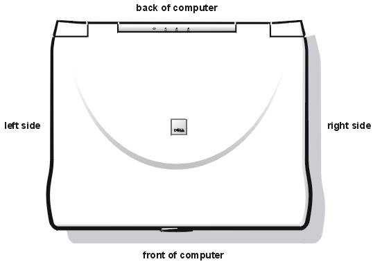
Also, when performing the
procedures in this document, the locations or directions relative to
the computer are as
shown in Figure 1 unless otherwise specified.
Figure 1. Computer Orientation
Recommended Tools
Most of the procedures in this document require the use of one or
more of the following tools:
- # 1 magnetized Phillips-head screwdriver
- Small flat-blade screwdriver
Preparing to Work Inside the Computer
Before you start to work on the computer, perform the following
steps.
NOTICE: Failure to perform the following steps could result in
damage to the computer.
NOTICE: If working inside your computer involves the removal of
the palmrest, note this information about the reserve battery. The reserve battery
provides power to the computer’s real-time clock (RTC) and nonvolatile random-access
memory (NVRAM) when the computer is turned off. Removing the palmrest disconnects the
reserve battery and causes the computer to lose the date and time information as well as
all user-specified parameters in NVRAM. If possible, make a copy of this information
before you disconnect the reserve battery.
- Save any work in progress and close all open application programs.
- Turn off the computer and any attached peripherals.

|
NOTE: Make sure that the computer
is turned off and not in save-to-disk suspend (S2D) mode. If you cannot shut down the
computer using the computer’s operating system, press the power button for 4 seconds.
|
- If the computer is docked in an advanced port replicator (APR), undock the computer.
- Disconnect the computer and any attached peripherals from their electrical outlets to
reduce the
potential for personal injury or shock.
Also disconnect any telephone or telecommunications lines from the
computer.
- Remove the power cable.
- Disconnect all other external cables from the computer.
- Remove any installed PC Cards.
NOTICE: Make sure that the work surface is clean to prevent
scratching the computer cover.
NOTICE: To avoid damaging the system board, remove the
power cable, the battery, and the
second battery (if installed) before you service the
computer.
- Remove the main battery assembly from the battery bay:
- Slide the battery bay latch toward the unlock icon.
- Slide the battery out of the battery bay (see Figure 2).
Figure 2. Main Battery Assembly Removal
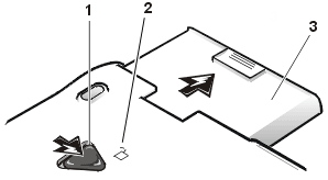 |
1 |
Battery bay latch |
| 2 |
Unlock
icon |
| 3 |
Battery |
|
|
- Ground yourself by touching the unpainted metal surface of the I/O
panel on the back of the computer.
While you work, periodically touch the I/O panel to dissipate any
static electricity that might harm components.
Screw Identification and Tightening
The illustrations in the following removal procedures provide the
correct screw length as part of the screw’s label.
A graphic for that length screw is
also included in the illustration.
Examples are shown in Figure 3. Match the actual screw to the graphic in the illustration to
check for correct length.
Figure 3. Screw Identification

NOTICE: When reinstalling a screw, you must use a screw of the
correct diameter and length. Otherwise, hardware damage could result. Make sure that the
screw is properly aligned with its corresponding hole, and avoid over tightening.
When you are removing and replacing components, photocopy the Table
1 placement mat as a tool to lay out
and keep track of the component screws.
Table 1. Screw Placement Mat With Component
Screw Counts
and Sizes
Hard-Disk Drive:
M3 x 5 (1 each) |
Keyboard
Assembly:
M2.5 x 10 (7 each) |
Display Assembly:
M2.5 x 4 (3 each) |
Display Assembly Bezel:
Rubber screw
covers (4 each)Plastic screw
covers (2 each) |
Display Assembly Bezel:
M2.5 x 4 (6 each) |
14.1 Display
Assembly LCD to Top Cover:
M2 x 3 (6 each) |
12.1-Inch Display
Assembly LCD to
Top Cover:
M3 x 5 (4 each) |
12.1-Inch Display
Assembly Inverter:
M3 x 3 (3 each) |
Palmrest Assembly:
M2.5 x 20 (5 each) |
System Board:
M2.5 x 4 (2 each) |
Microprocessor Shield:
(three captive and
two removable screws)
M2 x 3 (2 each) |
TCA and
Exhaust Fan:
M2.5 x 4 (2 each) |
ZIF Connectors
Some of the computer’s interface connectors are zero insertion
force (ZIF) connectors. These connectors are not removable, but they must be released to
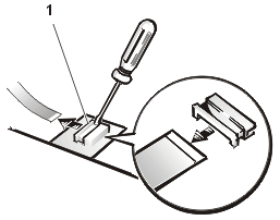
disconnect a cable from them (see Figure 4).
Figure 4. Disconnecting an Interface Cable
 |
|
|
|
|
| 1 |
Movable part of connector (do
not remove) |
|
|
NOTICE: The ZIF connectors are fragile. To avoid damage, do not
apply too much pressure to the movable part of the connector.
To disconnect an interface cable from a ZIF connector, perform the following
steps:
- Insert a small flat-blade screwdriver behind the movable part of the
connector.
- Push gently sideways on the movable part of the connector until it
releases the interface cable.
- Grasp the interface cable and pull it out of the connector.
To reconnect an interface cable to a ZIF connector, perform the following
steps:
- Use a small flat-blade screwdriver to open the movable part of the
ZIF connector.
- Orient the end of the interface cable with the ZIF connector, and
insert the end of the cable into the connector.
- While holding the cable in place, close the ZIF connector.
- To ensure a firm connection, make sure the ZIF connector is
completely closed.
Removing Field-Replaceable Parts
and Assemblies
Figure 5. Exploded View — Computer
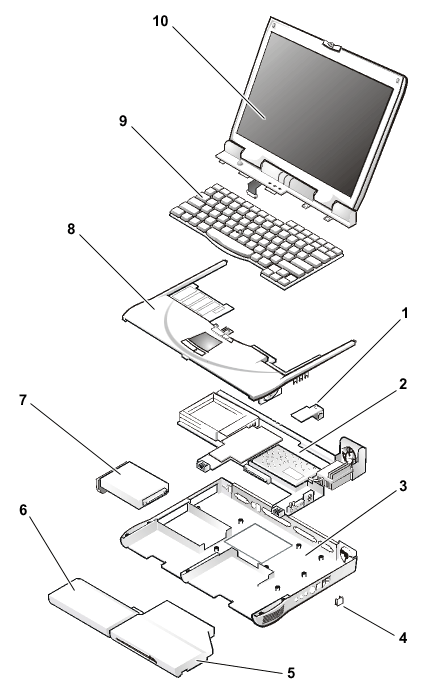 |
1 |
Modem (may not
apply to your system) |
| 2 |
System board |
| 3 |
Bottom case
assembly |
| 4 |
Case plug for
modem (may not apply to your computer) |
| 5 |
Media bay device |
| 6 |
Main battery |
| 7 |
Hard-disk drive
assembly |
| 8 |
Palmrest assembly |
| 9 |
Keyboard |
| 10 |
Display assembly |
The following sections provide instructions for removing and
replacing field-replaceable parts and assemblies.
Hard-Disk Drive
Assembly
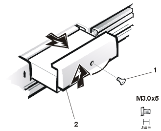
Figure 6. Hard-Disk Drive Assembly
 |
|
|
|
|
| 1 |
5-mm screw |
| 2 |
Hard-disk drive
bezel |
|
|
|
|
To remove the hard-disk drive assembly, perform the following steps.
NOTICE: To avoid damaging the system board, remove the
power cable, the battery, and the second battery (if installed) before you service the
computer.
NOTICE: The hard-disk drive is very sensitive to shock. Handle the
assembly by its edges (do not squeeze the top of the hard-disk drive case), and avoid
dropping it.
NOTICE: Make sure that the work surface is clean to prevent
scratching the computer cover.
- Turn the computer over, and remove the 5-mm screw from the center of
the
hard-disk drive bezel (see Figure 6).
The drive is on the left side of the computer.
- Slide the drive bezel up and pull the drive out of the computer.
Media Bay Devices
You can install the following devices in the media bay:
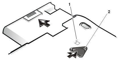
Figure 7. Media Bay Device Removal
|
|
|
|
|
|
|
| 1 |
Unlock icon |
| 2 |
Media bay latch |
|
|
|
|
|
|
To remove a media bay device, perform the following steps.
NOTICE: Make sure that the work surface is clean to prevent
scratching the computer cover.
- Close the display and turn the computer over.
- Push the media bay latch toward the unlock icon.
Keep holding the latch open while pulling the device out of the
media bay with the other hand (see Figure 7).
Memory Module Cover
To remove the memory module cover, perform
the following steps.
NOTICE: To avoid damaging the system board, remove the
power cable, the battery, and the second battery
(if installed) before you service the
computer.
NOTICE: Make sure that the work surface is clean to prevent
scratching the computer cover.
- Close the display, and turn the computer upside down on a flat work
surface.
- Release the memory module cover.
Insert a flat-bladed screwdriver under the indentation in the bottom
case assembly and lift the cover.
Memory Modules
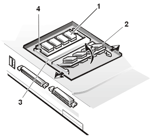
Figure 8. Memory Module Removal
|
|
| 1 |
DIMM A |
| 2 |
DIMM B |
| 3 |
Memory module
sockets (2) |
| 4 |
Inner tabs (2 per
socket) |
|
To remove a memory module, perform the following steps.
NOTICE: To avoid damaging the system board, remove the power
cable, the battery, and the second battery (if installed) before you service the computer.
- Remove the memory module cover.
NOTICE: To avoid possible damage to the memory module from
electrostatic discharge (ESD), ground yourself by touching the unpainted metal surface of
an I/O connector on the computer’s back panel.
- To release a memory module from its socket, carefully spread apart
the inner tabs of the memory module socket just far enough for the memory module to
disengage from the socket (it should pop up slightly) (see Figure 8).
- Lift the memory module out of its socket.
To install a memory module, perform the following steps:
NOTICE: If you only have one memory module, install it in the
DIMM A socket. Memory modules are keyed, or designed to fit into their sockets, in only
one direction. The slots on the system board are notched so that the memory module can be
firmly seated only one way.
- Align the memory module’s edge connector with the slot in the
center of the memory module socket.
- With the module at a 45-degree angle, press the memory module’s
edge connector firmly into the memory module socket.
- Pivot the memory module down until it clicks into place.
If you do not hear a click as each end of the memory module snaps
into the tabs, remove the memory module and reinstall it

|
NOTE: The 192-megabyte (MB) memory
modules are designed for either the socket labeled DIMM A or the socket labeled DIMM B;
however, they are not interchangeable. Be sure that the memory module is inserted with the
double-stacked memory chips facing you. A 192-MB memory module inserted with the
double-stacked memory chips facing down does not fit properly in the socket. |
Keyboard Assembly
To remove the keyboard assembly, perform the following steps.
NOTICE: To avoid damaging the system board, remove the power cable, the
battery, and the second battery (if installed) before you service the computer.
NOTICE: Make sure that the work surface is clean to prevent
scratching the computer cover.
- Close the display assembly, and turn the computer upside down on a flat work surface.
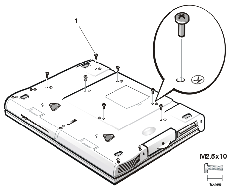
Figure 9. Removing the Keyboard Assembly
Screws
 |
|
|
|
|
| 1 |
10-mm screws (7) |
|
|
- Remove the seven 10-mm screws, labeled with a "circle K,"
that secure the keyboard to the computer (see Figure 9).
- Turn the computer right-side up and open the display.
NOTICE: The keycaps on the keyboard are fragile, easily
dislodged, and time-consuming to replace. Be careful when removing and handling the
keyboard.
- Release the keyboard from the palmrest assembly by inserting a small
flat-blade screwdriver under the edge of the blank key (see Figure 10), and lift the right
edge of the keyboard.
Figure 10. Keyboard Assembly Removal
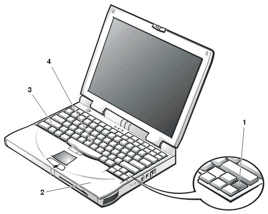
| 1 |
Scalloped edge if blank key |
|
|
| 2 |
Palmrest |
|
|
| 3 |
Keyboard |
|
|
| 4 |
Track stick |
|
|
- Lift the keyboard out of the palmrest.
- Rotate the keyboard over its left edge.
- Rest the key face of the keyboard on the left side of the computer
(see Figure 11).
Figure 11. Keyboard and Track Stick Cables
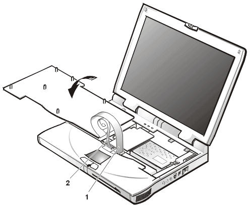 |
|
|
|
|
|
|
|
|
| 1 |
Keyboard cable |
| 2 |
Track stick cable |
|
|
|
|
|
|
|
|
- Disconnect the keyboard cable from the connector on the system board.
The keyboard cable is the wide, flexible cable.
- Carefully disconnect the track stick cable from the ZIF connector on
the palmrest’s flexible printed circuit (FPC).
- Remove the keyboard assembly.
To replace the keyboard assembly, perform the following steps.
NOTICE: Position the track stick and keyboard cables so that they
are not twisted when connected to the system board.
- Place the keyboard on the left side of the computer with its key face
down (see Figure 11).
- Connect the track stick cable to the ZIF connector.
Ensure that the contact side of the cable is down when you insert
the cable into the ZIF connector.
- Connect the keyboard cable to the connector on the system board.
- Carefully turn the keyboard over and fit the keyboard into place.
Ensure that the track stick and keyboard cables are not twisted as
you lower the keyboard into the palmrest.
- To push the keyboard down, press on the blank key located below the
<Shift> key on the right side of the keyboard.
- Check that the keyboard is correctly installed.
The keys should be flush with the left and right surfaces of the palmrest.
- Reinstall the seven 10-mm screws.
Start by installing the outermost screws on the left and right sides
of the computer, and then work inward to the center.
Microprocessor Module
Figure 12. Microprocessor Module Removal
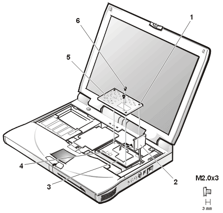
|
|
|
|
|
|
|
| 1 |
Captive screws
(3) |
| 2 |
Thermal cooling
assembly arm |
| 3 |
Microprocessor
module |
| 4 |
White marks on
the microprocessor board |
| 5 |
Microprocessor
shield |
| 6 |
3-mm screws (2) |
|
|
|
|
|
|
To remove the microprocessor module, perform the following steps.
NOTICE: To avoid damaging the system board, the power cable,
battery, and second battery (if installed) must be removed before you service the
computer.
- Remove the main battery.
- Remove the keyboard assembly.
NOTICE: To ensure maximum cooling for the microprocessor, do not
touch the heat transfer areas on the thermal cooling assembly (TCA). The oils in your skin
reduce the heat transfer capability of the thermal pads.
- Remove the two 3-mm screws on the microprocessor shield that secure
the thermal cooling assembly to the microprocessor module (see Figure 12).
- Loosen the three captive screws securing the microprocessor shield to
the microprocessor module.
- Remove the microprocessor shield.
- Rotate the arm of the thermal cooling assembly up and away from the
microprocessor module.
NOTICE: When removing the microprocessor module, pull the module
straight up. Do not move the tool from side to side to extract the processor board.
- Use a microprocessor extractor tool to remove the microprocessor
module.
The tool fits on the left side of the module aligned with white
marks on the front and back edge of the processor board (see Figure 12).
NOTICE: Proper seating of the microprocessor module requires a
considerable amount of force (approximately 35 pounds [16 kilograms]) applied above the
module connector. A microprocessor module that is not properly seated can result in an
intermittent connection and subsequent failures.
- Align the microprocessor connector on the left side of the board and
press down firmly on the metal plate that is directly over the connector.
When the microprocessor module is seated, all four corners must be
at the same height. If one or more corners of the module are higher than the others, the
module is not seated correctly.
- To ensure the microprocessor module is fully seated, apply pressure
directly over the corner without the mounting screw hole.
- Rotate the arm of the thermal cooling assembly into place.
- Replace the microprocessor shield.
- Replace the two 3-mm screws that secure the thermal cooling assembly
arm and shield to the microprocessor module.
- Tighten the three captive screws on the corners of the shield to
secure the microprocessor module and shield.
Display Assembly
Figure 13. Display Assembly
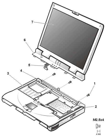
|
|
|
|
|
|
|
|
|
|
|
| 1 |
4-mm screws (3) |
| 2 |
Snap tab |
| 3 |
Bottom case
assembly |
| 4 |
Snap tab |
| 5 |
LCD flex cable |
| 6 |
Hinge cover |
| 7 |
Display assembly |
|
|
|
|
|
|
|
|
|
|
To remove the display assembly, perform the following steps.
NOTICE: To avoid damaging the system board, the power
cable, battery, and second
battery (if installed) must be removed before you service the
computer.
NOTICE: Do not remove the palmrest before you remove the
display.
- Remove the keyboard assembly.
- Close the display.
- Remove the three 4-mm screws, labeled with a "circle D," from the back of the
computer (see Figure 13).
- Open the display.
- Disconnect the liquid crystal display (LCD) flex cable from the connector on the system
board by pulling
the connector straight up.
- Lift the display assembly from the bottom case assembly.
- Pry the hinge cover loose at the seam from the snap tabs on the bottom assembly (see
Figure 13).
Display Assembly Bezel
Figure 14. 14.1-Inch Display Assembly
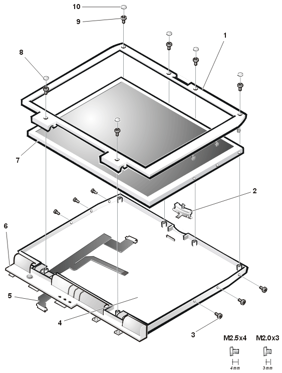
| 1 |
Display assembly bezel |
6 |
Hinge cover |
| 2 |
Latch |
7 |
LCD panel |
| 3 |
3-mm screws (6) |
8 |
Plastic screw covers (2) |
| 4 |
Display-assembly top cover |
9 |
4-mm screws (6) |
| 5 |
LCD flex cable |
10 |
Rubber screw covers (4) |
To remove the display assembly bezel, perform the following steps.
NOTICE: To avoid damaging the system board, remove the power
cable, the battery, and the second battery (if installed) before you service the computer.
- Use a scribe to carefully pry the four rubber screw covers out of the
four screw holes located at the top of the bezel on the front of the display assembly.
- Remove the four 4-mm screws located at the top of the bezel on the
front of the display assembly (see Figure
14).
- Use a scribe to carefully pry the two plastic screw covers out of the
two screw holes located at the bottom of the bezel on the front of the display assembly.
- Remove the two 4-mm screws from the bottom of the bezel.
NOTICE: The bezel tabs are fragile. Handle the bezel carefully to
avoid breaking the tabs off.
- Separate the bezel from the display-assembly top cover.
The bezel is secured by three tabs on the left and right side of the
display-assembly top cover.
14.1-Inch Display LCD
Panel
Removing the 14.1-Inch Display LCD Panel
To remove the 14.1-inch display LCD panel, perform the following
steps.
NOTICE: To avoid damaging the system board, remove the power
cable, the battery, and the second battery (if installed) before you service the computer.
- Remove the main battery.
- Remove the keyboard assembly.
- Remove the display assembly.
- Remove the display assembly bezel.
- Remove the three 3-mm screws on the left side of the LCD panel and
the three 3-mm screws on the right side of the LCD panel (see Figure 14).
- Lift and rotate the top of the LCD panel out of the top cover.
- Disconnect the ZIF connector and the display-assembly interface cable
connector (see Figure 4).
- Lift the LCD panel out of the top cover.

|
NOTES: Remove and replace the LCD
panel as a complete assembly.
Use a magnetic screwdriver to reassemble the LCD
panel in the display. Secure the right side first. |
Removing the 14.1-Inch LCD Flex Cable
- Remove the 4-mm screw securing the metal cable clip to the left hinge
of the display-assembly top cover (see Figure
14).
- Remove the cable out from under the plastic strain-relief retainer
located on the bottom of the display-assembly hinge cover.
- Remove the clip from the bottom of the hinge cover located at the
bottom of the display assembly.
- Pry the hinge-cover assembly apart from the display assembly,
allowing just enough space for the flex cable to pass through the opening.
- Slide the cable through the opening.
12.1-Inch
Display LCD Panel
Figure 15. 12.1-Inch Display
Assembly
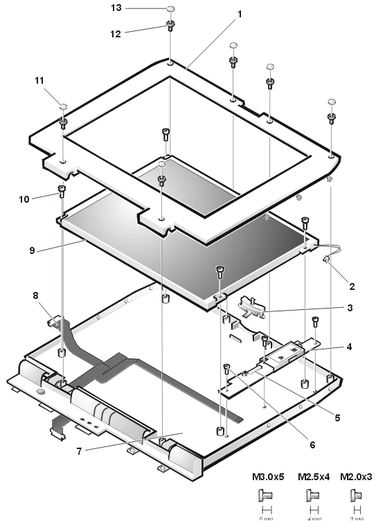 |
1 |
Display assembly bezel |
| 2 |
Back-light plug |
| 3 |
Latch |
| 4 |
Inverter |
| 5 |
ZIF connector |
| 6 |
3-mm screws (3) |
| 7 |
Display-assembly top cover |
| 8 |
LCD flex cable |
| 9 |
LCD panel |
| 10 |
5-mm screws (4) |
| 11 |
Plastic screw covers (2) |
| 12 |
4-mm screws (6) |
| 13 |
Rubber screw covers (4) |
|
|
Removing the 12.1-Inch Display LCD Panel
To remove the 12.1-inch display LCD panel,
perform the following steps.
NOTICE: To avoid damaging the system board, remove the power
cable, the battery, and the second battery (if installed) before you service the computer.
- Remove the main battery.
- Remove the keyboard assembly.
- Remove the display assembly.
- Remove the display assembly bezel.
- Remove the four 5-mm screws securing the LCD panel to the top cover
(see Figure 15).
- Disconnect the two-wire backlight plug from the connector on the
inverter.
- Lift the LCD panel and carefully disconnect the flex cable from the
connector on the left edge of the LCD panel.
- Remove the LCD panel from the top cover.
Removing the 12.1-Inch LCD Panel Inverter
- Disconnect the LCD flex cable from the
ZIF connector on the inverter.
- Remove the three 3-mm screws securing the inverter to the top cover.
- Remove the inverter from the top cover.
- Remove the 4-mm screw securing the metal cable clip to the left hinge
of the display-assembly top cover (see Figure
15).
- Remove the cable out from under the plastic strain-relief retainer
located on the bottom of the display-assembly hinge cover.
- Remove the flex-cable clip from the bottom of the hinge cover located
at the bottom of the display assembly.
- Pry the hinge-cover assembly apart from the display assembly,
allowing just enough space for the flex cable to pass through the opening.
- Slide the cable through the opening.
Replacing the 12.1-Inch LCD Flex Cable
- Pry the hinge-cover assembly apart from the display assembly,
allowing just enough space for the flex cable to pass through the opening.
- Slide the cable through the opening.
- Attach the flex-cable clip to the bottom of the hinge cover located
at the bottom of the display assembly.
- Slide the flex cable under the plastic strain-relief retainer located
on the bottom of the display-assembly hinge cover.
- Reinstall the 4-mm screw that secures the metal cable clip to the
left hinge of the display-assembly top cover.
- Find the manufacturer’s name on the back of the LCD panel that
is to be installed. The manufacturer is either Torisan or Sharp.
| NOTICE: The LCD flex cable must be
folded correctly before the cable connector can be attached to the connector on the LCD
panel. |
- Fold the LCD flex cable at the crease shown in Figure 16, so that the name of the LCD panel
manufacturer faces up.
The connectors on the Torisan and Sharp LCD panels are mounted in
the reverse of each other. This means that pin 1 on the Torisan panel connector is at the
opposite end when compared to pin 1 on the Sharp panel connector. Both panels have the
same connector, but the connector is mounted differently.
The LCD flex cable can connect to either panel by making one fold to
the cable. The words Torisan and Sharp are printed on the cable (see Figure 16). If you are installing a Torisan LCD
panel, fold the cable at the crease so the word Torisan is facing up. If you are
installing a Sharp LCD panel, fold the cable at the crease so the word Sharp is
facing up.
Figure 16. 12.1-Inch LCD Flex
Cable
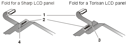 |
1 |
Curled back to connect to
panel |
| 2 |
LCD manufacturer name |
| 3 |
Crease (underneath) |
| 4 |
Crease (on top) |
Replacing
the 12.1-Inch LCD Panel Inverter
To replace the 12.1-inch display LCD panel inverter,
perform the following steps:
- Find the manufacturer’s name on the back of the LCD panel that
is to be installed. The manufacturer is either Torisan or Sharp.
| NOTICE: The inverter jumpers must be
configured to match the LCD panel that is installed. Improper jumper configuration can
cause damage to the LCD panel. |
- Ensure that the inverter’s configuration jumpers are set
correctly (see Figure 17).
If you are installing a Sharp LCD panel, both jumpers are used. If
you are installing a Torisan LCD panel, the bottom jumper is used. See the sticker on the
inverter shield for more information.
Figure 17. 12.1-Inch LCD Inverter
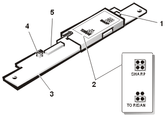 |
1 |
Backlight connector |
| 2 |
Label |
| 3 |
Inverter |
| 4 |
Jumpers |
| 5 |
ZIF connector |
|
|
- Place the inverter in the cover top.
- Reinstall the three 3-mm screws that secure the inverter to the top
cover.
- Connect the LCD flex cable to the ZIF connector on the inverter.
Replacing the 12.1-Inch LCD Panel
- Find the manufacturer’s name on the back of the LCD panel that is to be installed.
The manufacturer is either Torisan or Sharp.
- Make sure that the LCD flex cable is folded correctly to accommodate
the LCD panel being installed.
For more information, see "Replacing the 12.1-Inch LCD Flex Cable."
- Verify that the inverter jumpers are set to accommodate the LCD panel
being installed.
For more information, see "Replacing the 12.1-Inch LCD Panel
Inverter."
- Place the bottom edge of the LCD panel in the bottom of the top cover, and elevate the
top of the panel with your hand.
| NOTICE: The LCD flex cable must be
folded correctly before the cable connector can be attached to the connector on the LCD
panel (see Figure 16). |
- Carefully connect the LCD flex cable to the connector on the left
edge of the LCD panel.
The flex cable must be curled back to connect to the LCD panel (see
Figure 16).
Do not force the LCD flex cable into the connector. If you have
trouble, check to make sure the LCD flex cable is folded correctly and try again.
- Lay the LCD panel in the top cover.
- Connect the two-wire backlight plug to the connector on the inverter.
When the plug is all the way in the connector, the key slot in the
center of the plug should not be visible. If you can see the key slot, the plug is
not in the connector correctly. Pull the plug out, turn the plug over, and reinsert it
into the connector.
- Reinstall the four 5-mm screws to secure the LCD panel to the top
cover.
Display Assembly Latch
To remove the display assembly latch, perform the following steps.
NOTICE: To avoid damaging the system board, remove the power
cable, the battery, and the second battery (if installed) before you service the computer.
- Remove the display assembly bezel.
- Remove the LCD panel.
- Remove the display assembly latch by unsnapping the latch and captive
spring from the inside of the display-assembly top cover (see Figure 14).
Palmrest Assembly
The palmrest assembly consists of the touch pad and the palmrest. To
remove the palmrest assembly, perform the following steps.
NOTICE: The reserve battery provides power to the computer’s
RTC and NVRAM when the computer is turned off. Removing the palmrest disconnects the
reserve battery and causes the computer to lose the date and time information as well as
all user-specified parameters in NVRAM. If possible, make a copy of this information
before you disconnect the reserve battery.
Figure 18. Removing the Palmrest Assembly
Screws
 |
1 |
20-mm screws (5) |
|
|
|
|
|
|
NOTICE: To avoid damaging the system board, remove the power
cable, the battery, and the second battery (if installed) before you service the computer.
- Remove the main battery.
- Remove the device from the media bay.
- Remove the keyboard assembly.
NOTICE: The display assembly must be removed before you can
remove the palmrest.
- Remove the display assembly.
NOTICE: Make sure that the work surface is clean to prevent
scratching the computer cover.
- Turn the computer upside down on a flat work surface.
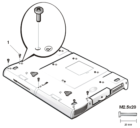
- Remove the five 20-mm screws that secure the palmrest to the
computer.
These screws, labeled with a "circle P," are located
underneath the front edge of the computer (see Figure 18).
- Turn the computer right-side up on the work surface.
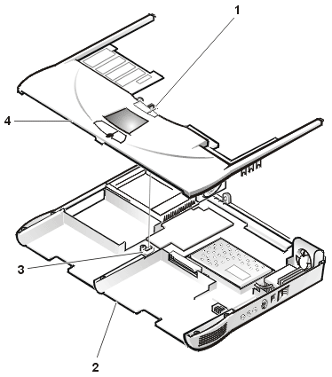
- Disconnect the palmrest flexible cable from the touch-pad connector
on the system board (see Figure 19).
Figure 19. Palmrest Assembly Removal
 |
|
|
|
|
|
|
|
|
| 1 |
Palmrest flexible
cable |
| 2 |
Bottom case
assembly |
| 3 |
Touch-pad
connector |
| 4 |
Palmrest assembly |
|
|
|
|
|
|
|
|
- Carefully remove the palmrest assembly from the bottom case assembly
(see Figure 19).
Reserve Battery
To remove the reserve battery, perform the following steps.
NOTICE: The reserve battery provides power to the computer’s
RTC and NVRAM when the computer is turned off. Removing the battery causes the computer to
lose the date and time information as well as all user-specified parameters in NVRAM. If
possible, make a copy of this information before you remove the reserve battery.
- Remove the main battery.
- Remove the device from the media bay.
- Remove the keyboard assembly.
- Remove the display assembly.
- Remove the palmrest assembly.
- Turn the palmrest assembly over.
- Remove the two 4-mm screws securing the palmrest bracket.
- Lift the palmrest bracket and turn it over, taking care not to twist
the touch-pad cable.
- Disconnect the reserve battery cable from the connector on the
palmrest bracket.
- Remove the reserve battery from the palmrest bracket:
- Tear the reserve battery free from the foam pad.
- Remove the remnants of the foam pad from the palmrest bracket.

|
NOTE: When you replace the reserve
battery, first connect the reserve battery cable to the connector on the palmrest bracket.
Then position the reserve battery on the palmrest bracket to minimize slack in the cable. |
Bay Latch Assemblies
Figure 20. Bay Latch Assemblies
 |
1 |
Bay latches (2) |
| 2 |
Springs (2) |
| 3 |
Bottom case assembly |
| 4 |
Bay latch buttons (2) |
| 5 |
Location of snap tabs (2) |
| 6 |
Sliders (2) |
|
|
To remove the bay latch assemblies, perform the following steps:
- Remove the main battery.
- Remove the device from the media bay.
- Remove the keyboard assembly.
- Remove the display assembly.
- Remove the palmrest assembly.
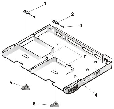
- Remove the left bay-latch button from the outside of the bottom case
assembly by carefully squeezing the snap tabs to unsnap the latch.
Keep pressure applied to the bay latch and spring while unsnapping
the snap tabs to prevent the bay latch assembly from coming loose from the case. If the
bay latch assembly does come loose from the case, perform the following steps:
- Carefully reinsert the spring onto the slider on the bay latch, and
reinstall the bay latch into the holding features on the inside of the case.
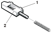
- Ensure that the slider is inserted in its respective hole, that the
side of the latch with the two bumps is facing the back of the case, and that the surface
with the wear ribs is facing the bottom of the case (see Figure 21).
- Snap in the new latch button from the bottom of the case, making
certain its snap tabs are fully engaged in the bay latch.
- Ensure that the newly installed latch moves smoothly and freely when
pushed and released.
- Repeat steps 6 through 8 for the latch on the right side.
Figure 21. Left Bay Latch and Spring
|
1 |
Bump side |
| 2 |
Wear ribs (2) |
|
|
|
|
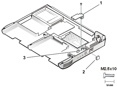
The modem assembly is optional. If present, you must remove
the modem before you can remove the system board (see Figure 22).
NOTICE: To avoid damaging the system board, you must
remove the main battery before you service the computer.
Removing the Modem Assembly
- Remove the main battery and secondary battery (if present).
- Remove the keyboard assembly.
- Remove the display assembly.
- Remove the palmrest assembly.
- Remove the 10-mm screw and washer securing the modem assembly.
Figure 22. Modem Assembly
|
|
|
|
|
|
|
| 1 |
Modem |
| 2 |
Case plug for
modem |
| 3 |
System board
connector for modem |
|
|
|
|
|
|
|
|
Replacing the Modem Assembly
- Press the RJ11 connector of the modem assembly into the hole in the
bottom case assembly.
- Carefully align and press the modem into the system board connector.
- Replace the internal modem 10-mm screw and washer (see Figure 22).
System Board Assembly
The system board’s basic input/output system (BIOS) chip
contains the system service tag number, which is also visible on a bar-code label on the
bottom of the computer. The replacement kit for the system board assembly includes a
diskette that provides a utility for transferring the service tag number to the
replacement system board assembly.
To remove the system board assembly, perform the following steps.
NOTICE: To avoid damaging the system board, remove the power
cable, the battery, and the second battery (if installed) before you service the computer.
- Remove the main battery.
- Remove the device from the media bay.
- Remove the keyboard assembly.
- Remove the display assembly.
- Remove the palmrest assembly.
- Remove the microprocessor module.
- Remove any PC Cards or plastic blanks from the PC Card slot.
- Verify that the PC Card ejectors do not extend from the PC Card slot.
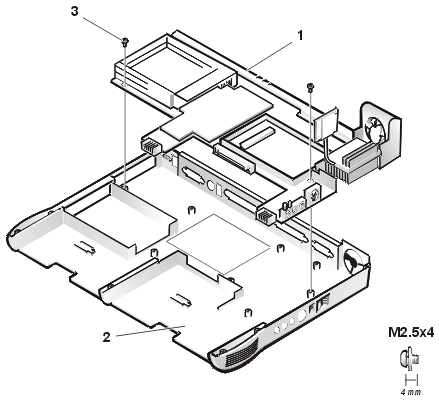
- Remove the following two screws from the system board assembly (see Figure 23):
- The 4-mm screw with captive washer located on the far left side of
the computer between the hard-disk drive assembly and the PC Card slot.
- The 4-mm screw with captive washer located on the far right side of
the computer in front of the thermal cooling assembly (TCA) and to the right of the
microprocessor module.

|
NOTE: Locate these screws by looking for the white
circles on the system board that outline the captive washers. |
Figure 23. System Board Assembly
|
|
|
|
|
|
|
|
|
| 1 |
System board
assembly |
| 2 |
Bottom case
assembly |
| 3 |
4-mm screws with
captive washers (2) |
|
|
|
|
|
|
|
|
- Lift the system board assembly out of the bottom case
assembly.
Be sure to transfer the memory module(s) to the replacement
system-board assembly.
Insert the diskette that accompanied the replacement system
board assembly into the diskette drive, and turn on the computer. Follow the instructions
on the display screen.
After replacing the system board assembly, be sure to enter
the system’s service tag number into the BIOS of the replacement system-board
assembly.
Thermal Cooling
Assembly
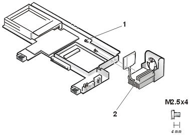
Figure 24. Thermal Cooling Assembly
|
|
|
|
|
|
|
|
|
| 1 |
4-mm screws (2) |
| 2 |
Thermal cooling assembly and
exhaust fan |
|
|
|
|
|
|
|
|
To remove the thermal cooling assembly, perform the following steps.
NOTICE: To avoid damaging the system board, remove the power
cable, the battery, and the
second battery (if installed) before you service the computer.
- Remove the main battery.
- Remove the device from the media bay.
- Remove the keyboard assembly.
- Remove the display assembly.
- Remove the palmrest assembly.
- Remove the microprocessor module.
- Remove the modem (if present).
- Remove the system board assembly.
- Disconnect the exhaust-fan power cable from the connector on the
system board.
- Remove the two 4-mm screws securing the thermal cooling assembly and
exhaust fan, and then remove the thermal cooling assembly and exhaust fan (see Figure 24).
Back to Contents Page
|
