System Board

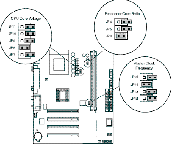
Jumper Locations:

JUMPER & SWITCH INFORMATION

Jumper Settings
Jumper 3
CMOS Normal CMOS Clear
pins 1-2 pins 2-3
Jumpers 4-6
JP4 JP5 JP6 CPU/Host Ratio
ON ON OFF 2.5
OFF ON OFF 3.0
ON OFF OFF 2.0
OFF OFF OFF 1.5/3.5
ON ON ON 4.5
OFF ON ON 5.0
ON OFF ON 4.0
OFF OFF ON 5.5

Jumpers 7-10
JP10 JP9 JP8 JP7 VCC2
OFF OFF OFF OFF 0
OFF OFF OFF ON 2.1
OFF OFF ON OFF 2.2
OFF OFF ON ON 2.3
OFF ON OFF OFF 2.4
OFF ON OFF ON 2.5
OFF ON ON OFF 2.6
OFF ON ON ON 2.7
ON OFF OFF OFF 2.8
ON OFF OFF ON 2.9
ON OFF ON OFF 3.0
ON OFF ON ON 3.1
ON ON OFF OFF 3.2
ON ON OFF ON 3.3
ON ON ON OFF 3.4
ON ON ON ON 3.5

Jumpers 12-15 CPU BUS SPEED
ON OFF OFF OFF 66.6mhz
OFF ON ON OFF 95mhz
OFF OFF ON OFF 97mhz
ON ON ON OFF 100mhz

REMOVAL & REPLACEMENT PROCEDURES - BEFORE YOU BEGIN

Step 1:

Preparation for Disassembly

To prepare the computer for removal and replacement procedures, complete the following steps:

1 Remove any diskette, compact disc, or tape from the computer.
2 Turn off the computer and any peripheral devices that are connected to the computer.

CAUTION: The computer power switch should be turned off before you disconnect any cables.

3 Disconnect the power cord from the electrical outlet, and then from the computer.
4 Disconnect all peripheral device cables from the computer.
IMPORTANT: During disassembly, label each cable as you remove it. Be sure to note its position and routing.
Step 2:

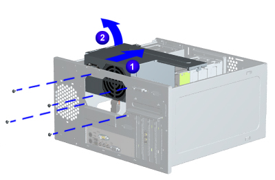
Remove Chassis

ai-2.jpg (50260  bytes)
Chassis
Removal
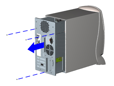
2 Remove the three screws from the back of the computer as shown.
3 With one hand, grasp the handle on the back of the computer chassis while holding the cover with the other hand, and pull until the chassis stops.
4 Lift up on the chassis and pull it completely out of the cover.
Replacement
To replace the chassis, reverse this procedure.

Step 3:

Remove Power Supply
aj-2.jpg (51788  bytes)
Power Supply
3 Gently lay the computer on its side (rear connectors should be closest to the working surface).
4 Remove the four screws that secure the power supply to the rear of the chassis as shown.
5 Slide the power supply away from the back of the chassis, flip it up and away, and slide it to the right to remove it from the slots.
Replacement
To replace the power supply, reverse this procedure.

Step 4:

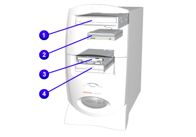
Remove Floppy Drive
hd.jpg (43014  bytes)
Mass Storage Devices - Index Page
1 CDRom/DVD Drive
2 3.5" or 5.25" Hard Drive
3 Zip Drive (only on selected models, not on 7471)
4 Diskette Drive

Step 5:

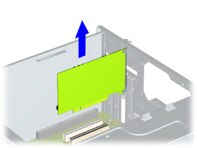
Remove Fax/Modem

en.jpg (51468  bytes)
Fax/modem
Removal
4 Remove the screws holding the option card bracket to the chassis.
5 Remove the bracket and pull the fax/modem out of the slot.
Replacement
  To replace the fax/modem, reverse this procedure.

Step 6:

Remove Memory Modules
eq.jpg (81233  bytes)
System Board Components

Memory Module (DIMM)

Removal
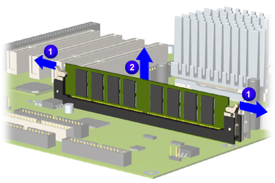
7 Release the retention clips of the socket and unplug the DIMM from the system board.

Replacement

To replace the DIMM, reverse this procedure

Step 7:

Remove Cables and System Board Screws
System Board Components

System Board

Removal
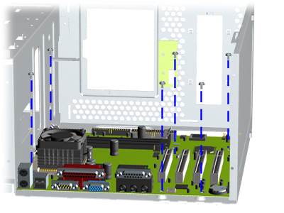
8 Remove all cables form the system board.
9 Remove the six screws from the system board (may differ slightly from photo) and separate it from the bracket.
Replacement
  To replace the system board, reverse this procedure.
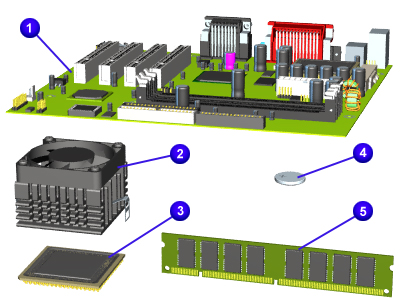
NOTE: The system board spare part kit does not include the processor, cache, DIMM, or video expansion module. The components must be transferred from the old system board to the new system board.