|
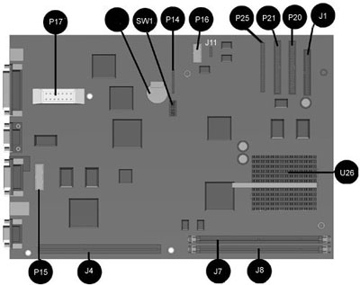
| Item |
Description |
Item |
Description |
| J1 |
Diskette Drive Connector (34 Pin) |
SW1 |
Processor Speed Switches |
| P20 |
Primary IDE Connector (40 Pin) |
P17 |
Power Supply Connector |
| P21 |
LS-120 Connector (40 Pin) |
P15 |
AUI Connector* |
| P25 |
CD-ROM Connector (50 Pin)** |
J4 |
Riser Board Socket |
| J11 |
Audio Connector |
J7 |
DIMM Socket |
| P16 |
Power Cable and LED Connector |
J8 |
DIMM Socket |
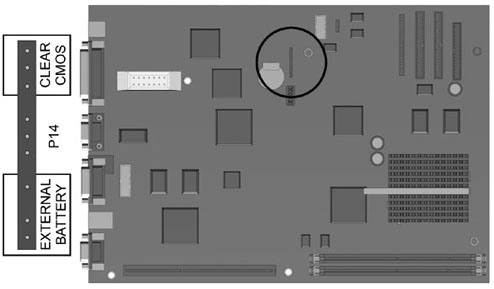
| P14 |
External Battery, Clear CMOS jumpers |
U26 |
Processor Socket |
Note:
*The AUI connector on the back of the unit connects to the system board
via a cable.
All other external connectors are integrated onto the system board.
** The CD ROM connector is specific to the Deskpro 4000s only.
This 50 pin connector is not an IDE connector, but a proprietary connector
in which the power to the drive is ran in the same cable. |


